Installation / User Manual APsystems YC600 Microinverter Rev 2.2 (For USA) ALTENERGY POWER SYSTEM Inc. usa.APsystems.com APsystems America 600 Ericksen Ave NE, Suite 200 Seattle, WA 98110 TEL: 844-666-7035 EMAIL: info.usa@APsystems.com Please scan the QR code to get mobile app and more support to help the installation.
Table of Contents 1.Important Safety Instructions.......................................................................................................... 2 1.1 Safety Instructions.......................................................................................................................................... 2 1.2 Radio Interference Statement........................................................................................................................ 3 1.
1.Important Safety Instructions This manual contains important instructions to follow during installation and maintenance of the APsystems Photovoltaic Grid-connected Inverter (Microinverter).
1.Important Safety Instructions 1.2 Radio Interference Statement FCC/IC Compliance : The equipment can comply with the limits for a class B digitaldevice,pursuant to part 15 of the FCC Rules, which are designed to protect against harmful interference in a residential installation. The equipment could radiate radio frequency energy and this might cause harmful interference to radio communications if not following the instructions when installing and using the equipment.
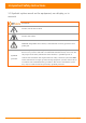
1.Important Safety Instructions 1.3 Symbols replace words on the equipment, on a display, or in manuals Trademark. Caution, risk of electric shock. Caution, hot surface. NOTICE, danger!This device directly connected with electricity generators and public grid. Person adequately advised or supervised by an electrically skilled person to enable him or her to perceive risks and to avoid hazards which electricity can create.
2.
2.APsystems Microinverter System Introduction This integrated system improves safety; maximizes solar energy harvest; increases system reliability, and simplifies solar system design, installation, maintenance, and management. APsystems Microinverters maximize PV energy production Each PV module has individual Maximum Peak Power Tracking (MPPT) controls, which ensures that the maximum power is produced to the utility grid regardless of the performance of the other PV modules in the array.
3.APsystems Microinverter YC600 Introduction The APsystems YC600 Microinverters connects with the single-phase grid, and can also use multiple APsystems Microinverters in the form of single-phase grid to achieve three-phase grid, and operates with most 60 and 72 cell PV modules. Contact APsystems Customer Support for checking compatibility.For more information, please see the Technical Data page (p.
4.APsystems Microinverter System Installation A PV system using APsystems Microinverters is simple to install. Each Microinverter easily mounts on the PV racking, directly beneath the PV module(s). Low voltage DC wires connect from the PV module directly to the Microinverter, eliminating the risk of high DC voltage. Installation MUST comply with local regulations and technical rules. ① Perform all electrical installations in accordance with local electrical codes.
4.APsystems Microinverter System Installation 4.3 Installation Procedures 4.3.1 Step 1 - Verify the grid voltage to match with microinverter rating 4.3.2 Step 2 - The AC bus distribution a. The AC bus is arranged at the proper position of the inverter. b. One end of the AC bus access junction box into power grid. c. Wire the conductors of the AC bus: L1 - BLACK ; L2 - RED;PE - GREEN.
4.APsystems Microinverter System Installation 4.3.4 Step 4 - Ground the systems a. There already has earth wire inside the AC cable, thus the grounding work could be done b. directly by it. For those areas that have special requirements, the external grounding work could be done by grounding brackets. grounding brackets Figure 3 4.3.5 Stpe 5 - Connect the APsystems microinverter to AC bus cable Push the microinverter AC connector to the trunk cable connector. Listen for the "Click".
4.APsystems Microinverter System Installation 4.3.6 Step 6 - Install a Bus Cable End Cap at the end of AC bus cable a. Strip cable jacket. c. Insert the wires into the cable clamps. b. Insert the cable end into the seal. d. Rotate the nut with 3.3N·m until the latching mechanism meets the base. Nut Seal Figure 8 Body 4.3.7 Step 7 - Connect APsystems Microinverters to the PV Modules Figure 9 When plugging in the DC cables, the microinverter should immediately blink green three times.
4.APsystems Microinverter System Installation 4.3.8 Step 8 - Complete the APsystems installation map Fill in the APsystems Registration Cards, which provide system information and the installation map. Feel free to provide your own layout if a larger or more intricate installation map is required. The layout map provided is designed to accomodate labels in vertical or horizontal orientation to meet all the field PV connections. a. Each APsystems Microinverter has removable serial number labels. b.
4.APsystems Microinverter System Installation APsystems Microinverter&Energy Communication Unit Warranty Card The APsystems Installation Map is a diagram of the physical location of each microinverter in your PV installation. Each APsystems microinverter has a removable serial number label located on the mounting plate. Pee l the label and affix it to the respective location on the APsystems installation map.
5.APsystems microinverter system operating instructions To operate the APsystems microinverter PV system: 1. Turn ON the AC circuit breaker on each microinverter AC branch circuit. 2. Turn ON the main utility-grid AC circuit breaker. Your system will start producing power after a two-minute waiting time. 3. The units should start blinking green every 2 seconds five minutes after turning on the AC circuit breaker. This means they are producing power normally, but have not yet connected to the ECU.
6.Troubleshooting Qualified personnel can use the following troubleshooting steps if the PV system does not operate correctly: 6.1 Status Indications and Error Reporting 6.1.1 Start up LED One quick red light followed by three short green blinks when DC power is first applied to the Microinverter indicates a successful Microinverter startup. 6.1.2 Operation LED Flashing Slow Green (10 sec. gap) - Producing power and communicating with ECU Flashing Fast Green (2 sec.
6.Troubleshooting 6.2 Troubleshooting a non-operating APsystems Microinverter There are two possible overall areas of trouble: A. The Microinverter itself may be having problems. B. The Microinverter itself is working fine but it is having trouble communicating with the ECU. The items below refer to Microinverter issues, not communication issues (addressed in the ECU manual). A quick way to tell whether the issue is the Microinverter or a communication problem with the ECU: 1.
7.Replace a microinverter A. Follow the procedure to replace a failed APsystems Microinverter Disconnect the APsystems Microinverter from the PV Module, in the order shown below: 1. Disconnect the AC by turning off the branch circuit breaker. 2. Disconnect the inverter AC connector from the AC Bus. 3. Disconnect the PV module DC wire connectors from the microinverter. 4. Remove the Microinverter from the PV array racking. B. Install a replacement Microinverter to the rack.
8.Technical Data ①. Be sure to verify the voltage and current specifications of your PV module match with those of the Microinverter. Please refer to the datasheet or usermanual which can be download from APsystems website www.APsystems.com. ② . You must match the DC operating voltage range of the PV module with the allowable input voltage range of the APsystems Microinverter. ③. The maximum open circuit voltage of the PV module must not exceed the specified maximum input voltage of the APsystems.
8.Technical Data SA10: Low/High Frequency Ride Through (L/H FRT) and Must Trip Settings Region Range Ride-Through Ride-Through of Adjustability Until (s) Operational Mode Trip Time (S) (Hz) High Frequency 2 (HF2) 62.0 - 64.0 No Ride-Through Not Applicable 0.16s High Frequency 1 (HF1) 60.1 - 62.0 299s Mandatory Operation 300s Not Applicable Indefinite Continuous Operation Not Applicable Low Frequency 1 (LF1) 57.0 - 59.9 299s Mandatory Operation 300s Low Frequency 2 (LF2) 53.
8.1 YC600 Microinverter Datasheet Region Model Input Data (DC) USA YC600-NA Recommended PV Module Power (STC) Range 250Wp-440Wp+ MPPT Voltage Range 22V-48V Operation Voltage Range 16V-55V Maximum Input Voltage 60V Maximum Input Current 12A x 2 Maximum Input Short Circuit Current 13.2A Output Data (AC) Maximum Continous Output Power 548VA Peak Output Power 600VA Nominal Output Voltage/Range 240V/211V-264V Adjustable Output Voltage Range 160-278V Nominal Output Current 2.
8.1 YC600 Microinverter Datasheet Anti-Islanding Protection Yes Over Current Protection Yes Reverse DC Polarity Protection Yes Overload Protection Yes Warranty 10 Years Standard ; 25 Years Optional Certificate&Compliance UL1741;CSA C22.2 No. 107.1-16;CA Rule 21 (UL 1741 SA); FCC Part15; ANSI Safety And EMC Compliance C63.4;ICES-003 Grid Connection Complianc IEEE1547 NEC2014 & NEC2017 Section 690.11 DC Arc-Fault circuit Protection NEC Compliance NEC2014 & NEC2017 Section 690.
9.Wiring Diagram 9.
9.Wiring Diagram 9.
9.Wiring Diagram 9.
10.YC600 Accessory 10.
10.2 Accessories Summary Accessories Category 1 2 3 4 5 6 7 8 9 10 Bus Cable (Mandatory) AC Branch Extension Cable (Optional) Bus Cable End Cap (Mandatory) Bus Cable Y-CONN Cap (Optional) Bus Cable Unlock Tool (Mandatory) DC Male Connector Cap (Optional) DC Female Connector Cap (Optional) AC Connector (Male) (Optional) AC Connector (Female) (Optional) Energy Communication Unit(Optional) Part NO.
APsystems Microinverter &Energy Communication Unit Warranty Card The APsystems Installation Map is a diagram of the physical location of each microinverter in your PV installation. Each APsystems microinverter has a removable serial number label located on the mounting plate. Peel the label and affix it to the respective location on the APsystems installation map.