Aprilia Consumer Service Spa Technical Service and Training Release 4 july 99 RSV 1000 Technical Training Course RSV Mille This material is didactic and may be changed following the technical development of the product
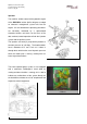
Aprilia Consumer Service Spa Technical Service and Training Release 4 july 99 RSV 1000 INTRODUCTION Open your third eye ! The originality of the technical decision the systematic use of solutions borrowed from the Racing Department and, above all, the passion and commitment applied to make every detail exclusive, form the basis of Aprilia's constructive philosophy.
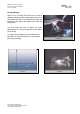
Aprilia Consumer Service Spa Technical Service and Training Release 4 july 99 Design Concept: Aprilia’s aim in making RSV Mille was to create a motorcycle with extremely compact dimensions, one that could cleave the air in an optimumn fashion and protect the rider against the impact of the wind and high speeds. The flow inside the front ait intakes has been optimazed too, as well as the position of the intakes on the fairing.
Aprilia Consumer Service Spa Technical Service and Training Release 4 july 99 THE ENGINE The engine fitted on the RSV Mille is a completely new type, conceived and developed by Aprilia's engineers. It is a 60°V-formation longitudinal two cylinder engine, with 4 distribution valves per cylinder and a double camshaft at the head, controlled by a mixed chain and gear system. lt is fed by electronic ignition with air input through a system of dynamic air intakes.
Aprilia Consumer Service Spa Technical Service and Training Release 4 july 99 The dry sump A further innovation brought by Aprilia in producing this new engine is the use of dry-sump lubrication, which allows a more rigid and compact engine block that the "wet-sump" solution. The system makes use of a second trochoid pump for recovery and an external oil tank, as well as a radiator positioned in front of the engine.
Aprilia Consumer Service Spa Technical Service and Training Release 4 july 99 lnjection The need for suitable control of the powerful engine of the RSV Mille led the Aprilia designers to adopt an electronic management system built into the engine. All the fondamental operating parameters are constantly monitored by a sophisticated electronic controls unit which, on the basis of the data received, control operation of both the injection system and the ignition system.
Aprilia Consumer Service Spa Technical Service and Training Release 4 july 99 The exhaust The exhaust system of the RSV Mille originates as the reply to four very precise requests: light weight, aerodynamic line, respect for the environment and for approval standards. The choice of the "2 in 1 " exhaust proved to be the most appropriate since, while obtaining an internal volume of over 9 litres, the bulk and weight are lower than those of a l'2 in 2" exhaust.
Aprilia Consumer Service Spa Technical Service and Training Release 4 july 99 As regards respect for the environment, the engine of the RSV Mille complies with the parameters of the future European standards (EURO 1, which comes into force in 1999); this result is achieved without the aid of any type of catalyst, as a further guarantee of performance and attention to these problems.
Aprilia Consumer Service Spa Technical Service and Training Release 4 july 99 CYCLE PARTS Jewel within the jewel, the cycle parts of the RSV Mille must be considered to all effects a true masterpiece of engineering. As beautiful as a work of art, impeccably but above all efficiently finished, instinctive and easy to drive, to quarantee optimum exploitation of all the engine power.
Aprilia Consumer Service Spa Technical Service and Training Release 4 july 99 COMPONENTS Every slightest detail of the RSV Mille receives the same meticulous care from Aprilia, to transfer dove, care and enthusiasm into every bike that the company produces.
Aprilia Consumer Service Spa Technical Service and Training Release 4 july 99 The Brakers: The Brakers of RSV, developed in close collaboration between Brembo and Aprilia, have calipers at the front with 4 piston with different diameters (34 and 30 mm) wich act on steel disks with diameter of 320 mm.
Aprilia Consumer Service Spa Technical Service and Training Release 4 july 99 SECTION 01: INJECTION SYSTEM 1.1 PREFACE: INTRODUCTION ON THE INJECTION-IGNITION SYSTEM The injection-ignition system is of the " alpha/n, D/J" type, in which motor speed and throttle position are used as the main parameters for the quantity of aspirated air; knowing the quantity of air, the fuel level is dosed as a function of the performance required.
Aprilia Consumer Service Spa Technical Service and Training Release 4 july 99 Operation phases. NORMAL OPERATION When the engine has a normal temperature, the control unit –ECU- calculates the phase, the injection time and the spark advance through interpolation of the corresponding store maps, as function of the r.p.m/pressure (..
Aprilia Consumer Service Spa Technical Service and Training Release 4 july 99 1.2 RSV 1000 FUEL INJECTION SYSTEM The main features of the RSV MILLE fuel injection system are as follows: 1. Possibility of setting the right air/fuel mixture in real time on the basis of the throttle valve opening, the inlet manifold pressure and the engine running speed. 2. Improved performance and acceleration response thanks to the SW which compensates the air/fuel mixture in all engine running conditions. 3.
Aprilia Consumer Service Spa Technical Service and Training Release 4 july 99 The control unit software switches between the DJ map and the alpha/n map on the basis of the engine running conditions. The injection volume also depends on the other factors provided by the compensation devices, illustrated later on.
Aprilia Consumer Service Spa Technical Service and Training Release 4 july 99 Compensation devices: Positioned inside the control unit box. Reads the Patm. The control unit normally reduces the injection volume in low atmospheric pressure conditions 1. Atmospheric pressure sensor 2. Engine coolant temperature sensor This sensor reads the coolant temperature. If the temperature reading is low, the control unit increases the injection times 3.
Aprilia Consumer Service Spa Technical Service and Training Release 4 july 99 - Timing control The times are controlled by the reading of the position of the crankshaft and the position of the camshaft. The control unit also detects the starting phase, injecting the fuel into the cylinders asynchronously.
Aprilia Consumer Service Spa Technical Service and Training Release 4 july 99 Injection stop control Rpm limiter: Software control. The control unit stops the injection if the rpm are excessive. Deceleration: The injector function is disabled during deceleration with the throttle valve closed.
Aprilia Consumer Service Spa Technical Service and Training Release 4 july 99 Safety systems Kick back Prevention: At about 300 rpm (if the rpm have been over 800 rpm) the control unit deenergizes the coil signal to prevent a possible kick-back in the pistons when turning the bike off. Tip over sensor: If the bike tips over, the tip over sensor stops the injectors’ control signal and fuel pump. The sensor is a mechanical switch already used on other bikes on the market.
Aprilia Consumer Service Spa Technical Service and Training Release 4 july 99 1.3 SELF-DIAGNOSTICS FUNCTION: The self-diagnostics function is part of the ECU software and is a valid aid to trouble-shooting in the electronic injection system.
Aprilia Consumer Service Spa Technical Service and Training Release 4 july 99 2-If everything is functioning perfectly, the following figures may appear on the display: -1, 0, 1 (throttle valve opening standard values – SEE CO SETTING) 3- If there are any faults, the fault codes will appear in sequence. The sequence will keep repeating until you exit the Dealer Mode.
Aprilia Consumer Service Spa Technical Service and Training Release 4 july 99 1.
Aprilia Consumer Service Spa Technical Service and Training Release 4 july 99 TROUBLE SHOOTING: WHAT TO DO IF THE ENGINE DOESN’T START AND NO FAULT IS SHOWN ON THE SELF-DIAGNOSTICS SYSTEM - Check the fuel pump Check the injectors Check that the anti-theft system connector is connected Check the key switch Check the STOP-RUN control Check the 30 Amp fuses and 15 Amp fuses B and E Check the engine stop relay Check the battery Check the safety system logic (diode box, switches) This material is didactic and
Aprilia Consumer Service Spa Technical Service and Training Release 4 july 99 START AND RUN POSSIBILITY: If a fault is detected, the control unit may: - stop the bike allow running but not starting allow running and starting as described in the table: FAILURE START POSSIBILITY RUN POSSIBILITY CAMSHAFT SENSOR NOT POSSIBLE POSSIBLE CRANKSHAFT SENSOR NOT POSSIBLE NOT POSSIBLE MANIFOLD PRESSURE SENSOR OR PRESSURE SENSOR SIGNAL POSSIBLE POSSIBLE THROTTLE POSITION SENSOR POSSIBLE POSSIBLE COOL
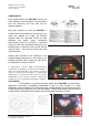
Aprilia Consumer Service Spa Technical Service and Training Release 4 july 99 OPERATION - DASHBOARD KEYS [A] [B] [R] [C] [D] 1. SEGMENTS OPERATION CHECK: Press keys [A] and [B] and turn the key from OFF to ON: all segments stay lit as long as [A] and [B] are pressed. 2. KM/H, MPH Press key [A] for 5 seconds =:> numbers and km/h (mph) flash Press key [B] to change unit of measurement Confirm with [A] pressed for about 5 seconds. 3.
Aprilia Consumer Service Spa Technical Service and Training Release 4 july 99 6. MULTIFUNCTION Coolant temperature and clock => [D] => Battery voltage => [D] => Set hours (Press LAP) => Set minutes (Press LAP) => Set °C/°F (Press LAP) => go back to b) Stop watch Press and hold [LAP] and then (within 0.7 seconds) press key [D] to start the stop watch. b. b.2) 1) Press [LAP] ==> stop watch starts (the [LAP] key is not enabled for 10 sec.
Aprilia Consumer Service Spa Technical Service and Training Release 4 july 99 SECTION 2: IGNITION SYSTEM The ignition system is controlled by the control unit. The system is a normal one, known as a digital transistorised ignition system, which sets the correct timing on the basis of the engine rpm and throttle position. It is made up of the crankshaft sensor (pick up coil), control unit, two ignition coils and spark plugs.
Aprilia Consumer Service Spa Technical Service and Training Release 4 july 99 CONTROL STRATEGY In the ignition phase, the control unit reads the starting, as shown in the separate figure. BATTERIA The ignition phase starts in this way (asynchronous/synchronous phase): 1. The control unit reads: - coolant temperature throttle angle engine rpm Patm. Battery voltage RELE’ AVVIA M ECU These values determine the ignition time when the engine is started.
Aprilia Consumer Service Spa Technical Service and Training Release 4 july 99 2. Cylinder recognition The camshaft and pick up sensors send signals that are clipped by the ECU. The camshaft sensor sends one signal for each cycle IGNITION/EXPANSION-EXHAUST), corresponding to an angle of 720° (INT-COMPRESS- The camshaft sensor sends 12 signals for each rotation of the crankshaft, i.e. one signal every 60°.
Aprilia Consumer Service Spa Technical Service and Training Release 4 july 99 IGNITION: The HT coils control is linked to the pick up signal after the recognition of the cylinders (see figure above). At low rpm (< 540) the ignition is set by the clipped signal of the pick up. The CPU gives consensus to the ignition only. These are “fixed spark timing” and “ fixed dwell timing” conditions. At medium rpm levels, the spark dwell timing is fixed but the spark advance timing varies.
Aprilia Consumer Service Spa Technical Service and Training Release 4 july 99 SECTION 3 : DESCRIPTION OF ELECTRONIC INJECTION SYSTEM The RSV1000 electronic injection system is made up of the following components: 1. Electronic control unit 2. Sensors (shaft position, temperature, pressure...) 3. Actuators 4. Ignition coils 5. Fuel pump The ECU also contains the static-inductive ignition circuit.
Aprilia Consumer Service Spa Technical Service and Training Release 4 july 99 3.1 THE E.C.U.: ELECTRONIC CONTROL UNIT The injection system and ignition system operation are controlled by the Nippodenso ECU, code no. 265470 (not final!!!). The control unit is connected to the rest of the bike’s electrical system by two ‘fast’ connectors. As well as being fed with power and receiving signals from the sensors through these connectors, the control unit also controls the injectors and l.t.
Aprilia Consumer Service Spa Technical Service and Training Release 4 july 99 In addition, the following systems/components are inside the control unit: - coils/injectors control power circuit Atmospheric pressure sensor CO regulation trimmer Trimmer regolazione CO CO ECU SETTING This material is didactic and may be changed following the technical development of the product
Aprilia Consumer Service Spa Technical Service and Training Release 4 july 99 ECU ELECTRONIC WIRING DIAGRAM: This material is didactic and may be changed following the technical development of the product
Aprilia Consumer Service Spa Technical Service and Training Release 4 july 99 ONNECTORS: The control unit is connected to the electrical circuit by plug-in connectors that plug into the ECU printed circuit. The connectors connect the control unit to the sensors and actuators (injectors, coils) via the wiring. Also, most of the connected components can be tested via the connectors, using any type of good quality ohmic tester.
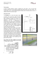
Aprilia Consumer Service Spa Technical Service and Training Release 4 july 99 SECTION 4 POSITIONING OF SENSORS AND INJECTORS: The position of each of the sensors is shown in the figure: This material is didactic and may be changed following the technical development of the product
Aprilia Consumer Service Spa Technical Service and Training Release 4 july 99 CAMSHAFT SENSOR: The cam sensor is an inductive sensor installed in the front cylinder head and is identical to the pick-up. This sensor is of fundamental importance and allows the ECU to recognise the exact sequence of each single cylinder, resetting the internal count to zero during the asynchronous ignition phase. The ohmic resistance of the sensor, measured at a temperature of 20 degrees, is about 240 Ohms.
Aprilia Consumer Service Spa Technical Service and Training Release 4 july 99 THROTTLE SENSOR: The throttle sensor, a highly reliable potentiometer, is a 4-pin resistive sensor. The sensor sends a voltage signal, proportional to the opening angle of the throttle valve, to the control unit. The sensor is positioned in the throttle assembly, as shown in the figure. The figure shows the sensor connections and the sensor resistance curve/angle.
Aprilia Consumer Service Spa Technical Service and Training Release 4 july 99 CRANKSHAFT SENSOR: PICK - UP An inductive sensor, already familiar from other models, positioned inside the magneto flywheel. Sends a voltage pulse to the control unit for every 60° of rotation and is of fundamental importance, together with the camshaft pulse, in allowing the ECU to set the injection and ignition times.
Aprilia Consumer Service Spa Technical Service and Training Release 4 july 99 TIP OVER SENSOR: This is a mechanical ring-switch which stays in contact with the plastic section as long as the bike is in a normal position. When the bike leans, the ring moves and, if the angle is greater than 44 degrees, it activates the switch terminals. A monitoring resistor is connected in parallel to the switch, for the control unit to check the connection to the component.
Aprilia Consumer Service Spa Technical Service and Training Release 4 july 99 ENGINE COOLANT TEMPERATURE SENSOR: This temperature sensor has a variable resistance which decreases with the increase in temperature. The ECU provides the sensor with a +5 Volt signal and measures the corresponding current, thus calculating the temperature, based on the characteristics of the sensor.
Aprilia Consumer Service Spa Technical Service and Training Release 4 july 99 MANIFOLD PRESSURE SENSOR: This sensor reads the pressure in the air cleaner box and provides a linear voltage in the range of 1 to 4.2 Volts to the control unit. It must be supplied with a continuous voltage of +5 Volts (provided by the control unit). The operating pressure ranges from13.3 to 120 Kpa (abs). The characteristic of the sensor is: Vo=Vcc*(0.006*Pi+0.
Aprilia Consumer Service Spa Technical Service and Training Release 4 july 99 INJECTORS: Each cylinder has an injector. The location in the throttle assembly is shown in the figure: The injector used is made up of the following components: 1. 2. 3. 4. 5.
Aprilia Consumer Service Spa Technical Service and Training Release 4 july 99 OTHER RELEVANT ELECTRICAL COMPONENTS: STARTER MOTOR: The characteristic operating curves are shown below: This material is didactic and may be changed following the technical development of the product
Aprilia Consumer Service Spa Technical Service and Training Release 4 july 99 DIODE MODULE: The figure shows the electrical wiring in the module. The continuity of the diodes can be checked with a tester or with a 4.5 - 12 Volt battery with an arbitrary load of max. 2 Watts. Remember that the diode conducts the current one way only, as indicated by the arrow representing the component in the diagram.
Aprilia Consumer Service Spa Technical Service and Training Release 4 july 99 VOLTAGE REGULATOR: The voltage regulator is situated at the rear of the bike on the right, in contact with the bodywork.
Aprilia Consumer Service Spa Technical Service and Training Release 4 july 99 TRASLATION OF LEGENDA FOR RS 1000 ELECTRIC WIRING DIAGRAM 1 2 3 4 5 6 7 8 9 10 11 12 13 14 15 16 17 18 19 ECU CAMSHAFT SENSOR THROTTLE SENSOR INTAKE AIR PRESSURE SENSOR WATER THERMISTOR (ECU) AIR THERMISTOR TIP OVER SENSOR DIODE MODULE CLUTCH SWITCH NEUTRAL SWITCH RELAY R1 RIGHT MAIN/DIPPED BEAM SELECTOR LEFT MAIN/DIPPED BEAM SELECTOR ENGINE STOP RELAY PUMP RELAY STARTER RELAY STARTER MOTOR BATTERY MAIN FUSES 20 21 22 23 24 25
Aprilia Consumer Service Spa Technical Service and Training Release 4 july 99 3.2 FUEL CIRCUIT The fuel circuit is made up of the following components: 1 fuel pump 2 fuel feed pipe 3 pressure regulator 4 injector. The fuel pump is immersed in the fuel tank and pumps the pressurised fuel to the feed pipe, where the pressure regulator keeps the fuel pressure about 3 bars higher than the intake pressure.
Aprilia Consumer Service Spa Technical Service and Training Release 4 july 99 The regulator - shown in the figure - has the following components: a vacuum-operated diaphragm and spring, and a steel ball valve with the valve seat mounted on the spring.
Aprilia Consumer Service Spa Technical Service and Training Release 4 july 99 POSITIONING OF ELECTRICAL COMPONENTS ON BIKE: VOLTAGE REGULATOR SPEED SENSOR This material is didactic and may be changed following the technical development of the product ECU COIL
Aprilia Consumer Service Spa Technical Service and Training Release 4 july 99 THROTTLE SENSOR ABS. PRESS.
Aprilia Consumer Service Spa Technical Service and Training Release 4 july 99 SECTION 5: ELECTRICAL CHECKS Refer to the key below when consulting this chapter: Ar= orange Az= light blue B= blue Bi= white G= yellow Gr= grey M= brown N= black R= red R= pink V= green Vi= purple V/Az Bi/R R/N Bi/R 30 A G 30 A R/B G G V V REG G V + CHECK 1.
Aprilia Consumer Service Spa Technical Service and Training Release 4 july 99 CHECK 3: H.T. COIL CHECK: Use the tester in the Ohms scale to check the continuity of the windings. The approx. values are as follows: L.T. SIDE: 3-6 OHMS H.T. SIDE: 12 – 15 KOHMS Note: This method is NOT able to detect partial failures in the isolation CHECK 4: TIP OVER SENSOR CHECK: Remove the sensor plus grommet from its housing and tilt it sideways at an angle greater than 45° to simulate a fall.
Aprilia Consumer Service Spa Technical Service and Training Release 4 july 99 Fitting the throttle sensor: (Please see section 9 for CO regulation) With the engine off, turn the ignition key to ON. When positioned in the throttle body, enable the control unit diagnostics function. If there are no errors (i.e. sensors all OK) one of three possible numbers will appear: +1: initial angle reading too high 0: throttle position OK -1: initial angle reading too low Turn the sensor until the 0 appears.
Aprilia Consumer Service Spa Technical Service and Training Release 4 july 99 CHECK 7: PRESSURE SENSOR CHECK: The readings below, taken one by Ohmmeter between 1-3 Ohmmeter between1-2 one, must give a value of 15 kOhms CHECK 8: DIODE MODULE CHECK: Disconnect the connector from the diode module and apply the circuit described below terminals, as listed in the table: Lampadina: 12V/2Watt + NEG The switching-on order must be as shown in the table: - \+ 1 1 X 2 3 4 5 This material is didactic and may be
Aprilia Consumer Service Spa Technical Service and Training Release 4 july 99 This material is didactic and may be changed following the technical development of the product
Aprilia Consumer Service Spa Technical Service and Training Release 4 july 99 CHECK 9: FUEL PUMP CHECK: Lift the fuel tank Disconnect the pump assembly 3 way connector Feed the green (+) and blue (-) wires coming from the side of the pump assembly with 12 Vdc. Ensure that the pump works by giving a buzz and checking that the fuel comes out of the throttle assembly (disconnect the tube).
Aprilia Consumer Service Spa Technical Service and Training Release 4 july 99 LIGHT WIRING DIAGRAM PASSING/LAP CLAXON LIGHTS LIGHTS P LIGHTS H H - Lo H – HI TURN R TURN L 32 67 A 31 D 29 FANALE POST.
Aprilia Consumer Service Spa Technical Service and Training Release 4 july 99 CHECK 10: WIRING AND COMPONENTS CHECK The main electrical components’ connections to the ECU are shown in the outline wiring diagram in fig.
Aprilia Consumer Service Spa Technical Service and Training Release 4 july 99 In more detail, the terminals refer to the components shown in the table; the standard ohmic values are also given: ECU CONNECTOR DESCRIPTION OF NUM.
Aprilia Consumer Service Spa Technical Service and Training Release 4 july 99 This material is didactic and may be changed following the technical development of the product
Aprilia Consumer Service Spa Technical Service and Training Release 4 july 99 This material is didactic and may be changed following the technical development of the product
Aprilia Consumer Service Spa Technical Service and Training Release 4 july 99 DASHBOARD ELECTRIC WIRING DIAGRAM: LEGENDA: D=15 AMP FUSE 53= FUEL WARNING LIGHT SENSOR 54= OIL PRESSURE SWITCH 55= WATER TEMP.
Aprilia Consumer Service Spa Technical Service and Training Release 4 july 99 CHECK 11: SPEEDOMETER CHECK: - Check the connections WITH THE ENGINE OFF: 1) With the key ON, measure the voltage between the green/purple and blue/orange wires without disconnecting the connectors. The reading should be more than 9 Volts dc. 2) Measure the voltage between the grey/white and blue/orange wires without disconnecting the connectors. The reading should be more than 6 Volts dc.
Aprilia Consumer Service Spa Technical Service and Training Release 4 july 99 This material is didactic and may be changed following the technical development of the product
Aprilia Consumer Service Spa Technical Service and Training Release 4 july 99 SECTION 6 FRAME The RSV1000 frame is a highly rigid aluminium structure, with a flexural rigidity of 650 Kgm/°.
Aprilia Consumer Service Spa Technical Service and Training Release 4 july 99 NOTE: FOR THE REMOVAL AND REFITTING OF THE ENGINE AND SWINGARM ON THE FRAME, SPECIAL WRENCHES MUST BE USED FOR UNSCREWING THE RING-TYPE LOCKNUTS ON THE 2 ENGINE FIXING POINTS (RH SIDE) AND ON THE RH SIDE OF THE SWINGARM PIN.
Aprilia Consumer Service Spa Technical Service and Training Release 4 july 99 SECTION 7 BRAKING SYSTEM The brakins systems of RSVmille are the best you can have on a production bike. Aprilia has developed them together with Brembo, company leader in this sector, and this braking systems offers an excellent MODULARITA’ through a 4 position adjusting lever. The braking pads are studied for informing the rider when the thickness of the braking element is lower than 1 mm.
Aprilia Consumer Service Spa Technical Service and Training Release 4 july 99 SECTION 8 REAR SHOCK ABSORBER The rear shock absorber of the RSVmille is a modern complete adjustable unit, like the front suspension. The shock absorber has a separate oil tank and a gas chamber to compensate the volume variations of oil due to temperature. Adjustments 1) Hydraulic functions The shock absorber can be registered separately for compression effect and rebound.
Aprilia Consumer Service Spa Technical Service and Training Release 4 july 99 This material is didactic and may be changed following the technical development of the product
Aprilia Consumer Service Spa Technical Service and Training Release 4 july 99 FRONT FORK SPECIFICATION BEARING PIPE DIAMETER: 43 mm STROKE: 127 mm REBOUND ADJ.: COMPRESSION EFFECT: MAX 2 TURN SPRING PRE-LOAD: MAX 2 TURN SPRING PRE-LOAD: MAX 25 mm // MIN. 10 mm SPRING OPERATION: 284 mm OIL Q.
Aprilia Consumer Service Spa Technical Service and Training Release 4 july 99 SECTION 09 PBTL SYSTEM The PBTL system on the RSV 1000 reduces the ‘braking’ torque transmitted by the engine during deceleration. OPERATING PRINCIPLE: Line 1 is connected to the intake passage whereas line 2 – downstream of the retaining valve – is connected to the airbox via the throttle valve. Line 3 links line 2 to the airbox when the throttle valve opens to an angle greater than 10-12 degrees.
Aprilia Consumer Service Spa Technical Service and Training Release 4 july 99 SECTION 10 TIMING SETTING OF RSV MILLE ENGINE REAR CYL # 2 FRONT CYL # 1 This material is didactic and may be changed following the technical development of the product
Aprilia Consumer Service Spa Technical Service and Training Release 4 july 99 1. FIXING CRANKSHAFT 1.1 REMOVE THE SCREW INDICATED WITH THE ARROW – CLUTCH SIDE 1.2 INSERT FIXING SCREW,AFTER REACHING THE TDC OF THE REQUESTED CYLINDER 1.3 DETAIL OF THE FIXING POINTS ON THE CRANKSHAFT ATTENTION !!! THE TIMING SETTING OF EACH CYLINDER MUST BE DONE AFTER POSITIONING THE FIXING SCREW ON THE RESPECTIVE T.D.C. (TOP DEAD CENTER) POINT.
Aprilia Consumer Service Spa Technical Service and Training Release 4 july 99 2. TIMING SETTING OF THE REAR CYLINDER (# 2) 2.1 ALIGNEMENT OF THE INTERMEDIATE GEAR USING THE PRINTED REFERENCES ON CRANKCASE 3. 2.2 ALIGNEMENT OF THE CAMSHAFT GEARS WITH THE PRINTED REFERENCES THE SCREWS OF THE LEFT GEAR (EXHAUST) ARE LONGER THE THOSE ON THE RIGHT 2.
Aprilia Consumer Service Spa Technical Service and Training Release 4 july 99 TIMING SETTING OF THE FRONT CYLINDER (# 1) 3.1 ALIGNEMENT OF CRANKSHAFT AND PRIMARY BALANCESHAFT WITH PAINTED REFERENCES 3.2 ALIGNEMENT OF INTERMEDIATE GEAR WITH THE PAINTED REFERENCE ON THE PLATE 3.
Aprilia Consumer Service Spa Technical Service and Training Release 4 july 99 SECTION 11: GENERAL DATA RSV MILLE TECHNICAL DATA This material is didactic and may be changed following the technical development of the product
Aprilia Consumer Service Spa Technical Service and Training Release 4 july 99 1.
Aprilia Consumer Service Spa Technical Service and Training Release 4 july 99 This material is didactic and may be changed following the technical development of the product
Aprilia Consumer Service Spa Technical Service and Training Release 4 july 99 2.
Aprilia Consumer Service Spa Technical Service and Training Release 4 july 99 3.
Aprilia Consumer Service Spa Technical Service and Training Release 4 july 99 4.
Aprilia Consumer Service Spa Technical Service and Training Release 4 july 99 4.FRAME TORQUE SETTINGS AIR FILTER BOX Description Qnty Screw\nut Nm Kgm M5 4 0,4 6 M6 8 0,8 4 SWP3,9 1 0,1 1 SWP3,9 1 0,1 Nm Kgm 80 8 Securing of the air box cover 7 Securing of the air box to the throttle body Securing of the air intakes Securing of the air sensor support ref. FRONT WHEEL Description Wheel axel nut Qnty Screw\nut 1 M25X1.5 ref. REAR WHEEL Description Nm Kgm ref.
Aprilia Consumer Service Spa Technical Service and Training Release 4 july 99 CLUTCH LEVER Description Nm Kgm Securing of the clutch lever liquid pipe Qnty Screw\nut 1 M10X1 20 2 Securing of the clutch liquid tank support 1 M6 12 1,2 Securing of the clutch liquid tank\clutch pump 1 M5 3 0,3 Clutch liquid bleeding valve 1 Nm Kgm 25 2,5 ref. EXAUST SYSTEM Description Securing the exaust pipes to the engine Qnty Screw\nut 3+3 M8 ref.
Aprilia Consumer Service Spa Technical Service and Training Release 4 july 99 Securing of intakes to the frame and to the support 14 SWP 3.9 Higer securing of lat.
Aprilia Consumer Service Spa Technical Service and Training Release 4 july 99 5 ENGINE TORQUE SETTINGS ENGINE CARTER Description (were and what) Nm Kgm ref.
Aprilia Consumer Service Spa Technical Service and Training Release 4 july 99 Valve cover cilinder 2- Cilinder head screw 2 M6X45 11 1,1 Valve cover cilinder 2- Cilinder head screw 2 M6X55 11 1,1 cilinder head 2- Locking screw 1 M18X1,5 Cilinder head\exhaust system- Stud screw 6 M8X16\20 10 1 L243 cilinder head 2- Oil bleeding valve 1 cilinder head\crunk- Stud screw 8 M10X171 15 1,5 Cilinder\cilinder head 8 M8X45 30 3 Cilinder head\stud- Hex.
Aprilia Consumer Service Spa Technical Service and Training Release 4 july 99 6 WIRING DIAGRAM This material is didactic and may be changed following the technical development of the product
Aprilia Consumer Service Spa Technical Service and Training Release 4 july 99 6.
Aprilia Consumer Service Spa Technical Service and Training Release 4 july 99 This material is didactic and may be changed following the technical development of the product