OWNER'S HANDBOOK LS Pro apricot MITSUBISHI ELECTRIC
OWNER'S HANDBOOK apricot Chapter
LOC Technology, KeyLOC and Integrated Network Architecture are trademarks of Apricot Computers Limited. Crystal and CrystalWare are trademarks of Crystal Semiconductor Corporation. AMD and PCnet are trademarks of Advanced Micro Devices. Microsoft and MS-DOS are registered trademarks, and Windows and Windows NT are trademarks, of Microsoft Corporation. Intel is a registered trademark, and Intel486, IntelDX4, Pentium and OverDrive are trademarks, of Intel Corporation.
Safety and Regulatory Notices Safety and Regulatory Notices The computer uses a safety ground and must be earthed. The system unit AC power cord is its “disconnect device”. Ensure that the system unit is positioned close to the AC power outlet, and that the plug is easily accessible. It is imperative that the system unit is set to the correct voltage range before use. If not, the machine may be irreparably damaged.
Safety and Regulatory Notices Safety If you wish to use the computer in another country, you must ensure that you use a power cord and plug which complies with the safety standards of that country.
Safety and Regulatory Notices UK plug wiring instructions This equipment is supplied with a mains lead that has a non-removable moulded plug. If the socket outlets are not suitable for the plug supplied with this appliance, it should be cut off and an appropriate three-pin plug fitted. Note: The plug severed from the mains lead must be destroyed, as a plug with the bared flexible cord is hazardous if engaged in a live socket outlet.
Safety and Regulatory Notices Safety Refer to the labels on the underside of the computer to establish which of the following warnings apply. FCC Class A Warning - this equipment has been tested and found to comply with the limits for a Class A computing device, pursuant to Subpart J of Part 15 of FCC rules. Only peripherals (computer input/output devices, terminals, printer, etc.) certified to comply with the Class A limits may be attached to this computer.
CONTENTS apricot Chapter
Contents CONTENTS 1 Introducing… Summary of features 1/1 Unpacking 1/3 Pictorial guide 1/6 Contents 2 Getting Started General advice 2/1 Connecting the components 2/2 Turning on and booting the computer 2/4 Backing up pre-installed software 2/9 Using the 3.
Contents Contents 6 Using the Security System Features of the security system 6/1 Configuring the security system 6/4 Setting up a security configuration 6/6 Defining user accounts 6/9 Understanding the logon sequence 6/14 Changing a password at logon 6/17 Unattended mode for Microsoft Windows 6/18 Telling users about the security system 6/19 7 Using PCMCIA Cards What is PCMCIA? 7/1 Installing PCMCIA cards 7/2 Inserting and removing PCMCIA cards 7/2 Configuring PCMCIA cards 7/4 8 Maintaining and Tran
Contents B Technical Information Specifications B/1 Physical characteristics B/2 Electrical characteristics B/2 Port characteristics B/3 System resources B/8 C Quick Guide To Security Contents LS PRO OWNER'S HANDBOOK III
INTRODUCING...
Introducing 1 INTRODUCING This chapter gives you a quick tour of your Apricot LS Pro computer. The initial summary of features is intended mostly for people who know a bit about computers and want to get an idea of what this one can do. But the unpacking instructions and pictorial guide will be helpful to everyone. Don’t worry if you’re unfamiliar with some of the computer terminology used in this chapter. It’s provided simply as a useful “shorthand” for more experienced readers.
Introducing • Integrated Network Architecture (INA): Advanced TM Micro Devices PCnet-32 VESA local bus Ethernet adapter with ports for thick, thin and twisted-pair Ethernet, and RPL (Remote Program Load) support in BIOS. • Enhanced Business Audio system: based on a Crystal Semiconductor CS4231 chipset (featuring 16-bit digital audio, stereo analog mixer and an Ad Lib-compatible FM synthesizer), with stereo input/output sockets and master volume control. • Apricot LOC Technology v2.
Introducing Advanced features The following advanced features are available on some models in the range: • 256 Kbyte external (second-level) memory cache. • 2 Mbytes of video memory (offering, for example, 800x600 resolution in 24-bit or ñtrueî colour). Unpacking On unpacking the computer, you should find: • Apricot LS Pro system unit. • Apricot/Mitsubishi monitor and accompanying UserÍs Guide. mono microphone. • System unit AC power cord and monitor power cord appropriate for the country of sale.
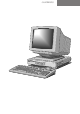
Introducing 1 2 3 4 5 apricot Chapter 1 6 Pictorial guide 1/4 LS PRO OWNER'S HANDBOOK
Introducing 1 POWER button: press to turn the system on or off. 2 power indicator: powered. 3 infrared sensor: detects the coded signals produced by a KeyLOC card (an optional hand-held infrared device that can be used with the security system).
1/6 LS PRO OWNER'S HANDBOOK 4 5 6 7 10101 1 2 PCMCIA 3 8 2 1 9 10 12 IEEE 802.
Introducing security loop: you can put a padlock through this loop to secure the top cover. 2 handle: to remove the top cover, remove the retaining screws at each side, then grasp and pull this handle firmly. 3 PCMCIA slots: suitable for all types of Personal Computer Memory Card International Association (PCMCIA) PC Card devices. 4 AC power outlet: where the monitor power cord can plug in.
Introducing 15 audio input socket: allows you to connect a microphone, a personal stereo (tape or CD), or a stereo line-in signal from a high-fidelity tape deck or CD player, to be used as a recording or monitoring source. 16 audio output socket: allows you to connect a stereo headset or a pair of self-powered speakers. Alternatively, it can provide a stereo line-out signal to a high-fidelity amplifier or tape deck.
Introducing 1 3 2 4 5 6 3.5" diskette drive (optional). 2 1" hard disk drive (optional). 3 ZIF (zero insertion force) processor socket: the current system processor can be replaced by a higher performance processor. 4 cache socket: a 256 kilobyte (Kbyte) external memory cache can be added if not already present. 5 SIMM sockets: the computerÍs base 4 megabytes of motherboard memory can be upgraded to 64 megabytes by the use of single in-line memory modules (SIMMs).
GETTING STARTED apricot Chapter Chapter 2
Getting Started 2 GETTING STARTED You should read this chapter even if you do not read any other. It provides important information to help you site, connect, power and configure the computer. This chapter will tell you all you need to know in order to start work. The chapters after this one deal with the special features of the computer: BIOS Setup, networking, audio and security. Warning Read the separate Power Connection Guide before using the computer for the first time.
Getting Started • Give the computer plenty of room so that air can circulate on all sides. Air is drawn into the system unit through the vent under the front bezel and expelled through a vent on the right-hand side. Ensure that these vents are never obstructed. • Do not allow any cables, particularly power cords, to trail across the floor where they can be snagged by people walking past. Warning The computer uses the system unit AC power cord as its “disconnect device”.
Getting Started Transporting”, for instructions on how to do this. It is likely that the monitor’s voltage setting will also need adjusting; consult the User’s Guide that accompanies the monitor, or ask your supplier for help. The “Safety and Regulatory Notices” section at the start of this Owner’s Handbook includes advice about suitable power cords.
Getting Started 6. Plug the mouse into the mouse port on the system unit. Never connect either the keyboard or the mouse while the system unit is turned on. 7. Where appropriate, connect the computer to the network. See Chapter 4, “Networking”, for guidance on connecting the computer to Ethernet networks. 8. Connect the monitor power cord between the monitor and the AC power outlet on the rear of the system unit. 9.
Getting Started but is more often a symptom of problems with the computer or its peripherals. Follow these steps: 1. Turn off the computer and unplug all power cords. 2. Unplug all peripherals. 3. Try to discover the cause of the fault. If none is apparent, replace the blown fuse with one of the same rating, reconnect the system unit power cord and try to turn it on again. 4. If the replacement fuse blows, call an authorized maintainer.
Getting Started If POST detects a hardware fault, one or more error messages are displayed. You may also be prompted to “Press the F1 key to continue.” Your first action should be to turn off the computer, wait at least 30 seconds, and then turn it on again to see if the error is transient or persistent. Persistent POST errors may indicate a fault in your system.
Getting Started partition, for different operating systems, but only one of these can be active at any one time. The computer loads its operating system from the currently active partition. Computers with a hard disk normally arrive with the Microsoft MS-DOS/Windows operating system already in place or preinstalled. If necessary, your operating system manuals should tell you how to format a blank diskette as a system diskette or how to partition and format a hard disk.
Getting Started Chapter 2 The following table lists some of the messages that might appear during the boot sequence. Message Explanation Non-system disk or disk error The diskette drive contains a non-system diskette. Replace it with a system diskette and press F1. Diskette read failure The diskette is either not formatted or defective. Replace it with a system diskette and press F1. No boot sector on fixed disk The hard disk has no active, bootable partition or is not formatted.
Getting Started 2. If you are logged-in to a network, logout before turning off your computer. This gives the network operating system a chance to free up the network resources you’ve been using. 3. Close down or quit any software that employs virtual memory or disk-caching (for example, Microsoft Windows with SMARTDrive). 4. Turn off any attached peripherals first, especially any peripheral attached to the parallel port.
Getting Started disk images present on the hard disk. Once you have done this, you can delete the disk images from your hard disk. See the utility’s on-line help for more information. To back up other pre-installed software, use Backup for DOS or Backup for Windows as described in your MS-DOS manual. It is a good idea to begin by creating a bootable system diskette containing the programs needed to partition and format the hard disk and to restore the backed up copy.
Getting Started Inserting a diskette A diskette is inserted into the diskette drive slot shutterforemost, and with its label side facing up (see diagram). To help you check the diskette is the right way round, there’s usually a small arrow on the face of the diskette which must point towards the drive when you insert it. Removing a diskette Before attempting to remove a diskette, make sure that the drive is not currently in use (the diskette activity indicator on the computer’s front bezel must be unlit).
Getting Started Write-protecting a diskette A diskette can be write-protected by sliding a small tab towards the edge of the diskette to expose the little hole beneath it (see diagram). With the tab in this position, you can read, copy or print files from the diskette, but you cannot create, rename or delete any files. PROTECTED UNPROTECTED The BIOS Setup utility can disable the diskette drive, or make it read-only.
Getting Started To configure (set up) a computer means to declare or describe its hardware components and to say how you want them to behave. Configuring your computer is necessary to ensure that the software you use can recognise and exploit the hardware’s capabilities. A record of the current configuration is kept in a special part of the computer’s memory, known as CMOS memory.
Getting Started For example, the files provided with the Apricot LS Pro include help on: • • • • Cirrus Logic CL-GD543x EVGA video drivers AMD PCnet-32 network drivers CrystalWare audio driver and utilities The Energy Star Programme Apricot Help may be supplied in various forms, depending on the intended operating system; for the Microsoft MS-DOS/ Windows operating system they are usually Windows help files or ASCII text files.
Getting Started 3. Choose the .HLP help file you want either by doubleclicking on its filename or by selecting the filename with the cursor and then pressing ENTER. The Windows Help program starts, displaying the first topic in the help file. Alternatively, you can copy the Windows help file from the diskette to a hard disk or network drive, and create a program item for it using Program Manager. The help file can then be viewed at any time simply by double-clicking on its icon.
Getting Started Viewing text files ASCII text files, identified by their .TXT file extensions, can be read by most text editors and wordprocessing programs. Alternatively they can be displayed, one screenful at a time, using the DOS commands type and more; for example: type helpfile.txt | more Version numbers Chapter 2 All the help files provided by Apricot have a version number so you can tell whether you’re looking at the most up-to-date version.
USING THE BIOS SETUP UTILITY apricot Chapter Chapter 3
Using the BIOS Setup utility 3 USING THE BIOS SETUP UTILITY BIOS Setup is a utility programmed into the computer’s readonly memory (ROM). Its main purpose is to allow you to view and alter the computer’s hardware configuration. It is also used to configure the on-board security system. The current configuration is kept in a special area of memory, called CMOS memory, and maintained by a small battery. BIOS Setup can be accessed whenever the computer is turned on or rebooted.
Using the BIOS Setup utility 4. Use the BIOS Setup dialog to set basic configuration options. Choose the Advanced button to set advanced configuration options. Choose the Security button to configure the security system (see Chapter 6). The Security button is greyed-out if your user account does not include the right to access the LOC Technology Setup dialog. BIOS Setup’s dialog boxes look like Microsoft Windows dialog boxes, and work in a similar way.
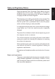
Using the BIOS Setup utility The following table lists the elements of BIOS Setup’s userinterface. Description Option groups An option group collects a number of related or exclusive items under a common heading. Buttons You choose a button to initiate the action described by the text on the button. Some buttons are marked with an ellipsis (...); choosing this kind of button opens another dialog box. Text boxes You can type words or numbers into a text box.
Using the BIOS Setup utility The simplest way to select or choose items is to point and click with a mouse. Note that the mouse is disabled while a text box is selected. If you prefer using the keyboard, you can use the following keystrokes: Press TAB To or SHIFT+TAB Move to the next or previous item in the dialog. To move directly to an item hold down the ALT key and press the character underlined in the item’s name. ARROW KEYS Move between the items within an option group.
Using the BIOS Setup utility Hard Disk The Disk 1 information box shows the type and capacity of the computer’s fixed hard disk drive, where known. Beneath this are three option buttons: Option Description None Select this if your computer does not have a fixed hard disk. This prevents the BIOS looking for a hard disk, and so speeds up the boot sequence. Autodetect Select this if your computer has a hard disk drive supplied by Apricot.
Using the BIOS Setup utility 3. If BIOS Setup cannot detect the drive type, you must manually enter the drive’s number of cylinders, heads and sectors, and its capacity, in the text boxes provided. 4. Choose the Save button. The Disk 2 entries in the BIOS Setup and User-defined Hard Disk dialogs are provided for future development; they are greyed-out in the current version. Floppy Disk The information box shows the type and capacity of the computer’s diskette drive.
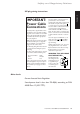
Using the BIOS Setup utility Power-on Sound When this option is enabled a tone will sound whenever the computer is turned on. To set the power-on sound: 1. In the Power-on Sound group, select the Enable check box. 2. Choose the Test button to audition the power-on sound. 3. Use the scroll bar to adjust the volume of the poweron sound as required. Power-on Password If this option is enabled a password must be entered every time the computer is turned on. To set a power-on password: 1.
Using the BIOS Setup utility Option Resolution and refresh rates SVGA 640x480 @ 60 Hz 800x600 @ 56 Hz 1024x768 @ 87 Hz Interlaced VGA/EVGA 640x480 @ 60 Hz 800x600 @ 72 Hz 1024x768 @ 70 Hz EVGA (high refresh) 640x480 @ 75 Hz 800x600 @ 75 Hz 1024x768 @ 75 Hz 1280x1024 @ 60 Hz Startup Chapter 3 The Startup options control how the display looks during POST, when BIOS sign-on and hardware configuration messages are displayed.
Using the BIOS Setup utility Option Description Local The computer looks for a system diskette or a bootable hard disk partition (in that order). Ethernet RPL The computer attempts to load an operating system from a server elsewhere on the network, using the on-board Ethernet adapter and the Remote Program Load (RPL) code in the BIOS ROM. PCMCIA Card This option is provided for future development of BIOS Setup; it is greyed-out in the current version.
Using the BIOS Setup utility Parallel Port These three options allow you to set the mode of the parallel port. Option Description Standard Standard IBM AT-compatible bidirectional “Centronics” mode. EPP Compatible Compatible with the Enhanced Parallel Port standard. ECP Compatible Compatible with the Microsoft/ Hewlett Packard Extended Capabilities Port standard. Disable These check boxes allow you to disable various motherboard features or components.
Using the BIOS Setup utility Option Meaning if selected Disables the diskette drive controller. Disables the computer’s ability to write to the diskette drive. Floppy Boot Disables the computer’s ability to boot from a system diskette in the diskette drive. Parallel Port Disables the parallel port, freeing interrupt IRQ7 and I/O ports 3BCh-3BFh. However, IRQ7 can usually be “double-booked” without affecting the operation of the parallel port.
Using the BIOS Setup utility Energy Conservation These options control the computer’s power management features. If you disable them, the computer’s system unit will no longer be Energy Star compliant (although the monitor may continue to comply). Option Meaning if selected Hard Disk Power Down Enables the feature that automatically spins down the hard disk after 20 minutes of inactivity.
NETWORKING apricot Chapter Chapter 4
Networking 4 NETWORKING The physical network connection is only the first step in establishing a networking environment; you will also need the appropriate network software. Consult your network documentation or the person (or department) responsible for administering the network. You must not attempt to connect your computer to the network without first informing the network administration or the other users of the network.
Chapter 4 Networking Apricot provides a comprehensive set of network drivers for the PCnet adapter. For more information, view the Apricot Help file that accompanies the drivers. Finding out about your network An Ethernet network may contain as few as two computers or many hundreds. Obviously, the size and complexity of your network will determine exactly how you should go about making the connection to it.
Networking 2. You will need to ensure that the adapter is correctly configured for your network. 3. Is there a nearby network outlet you can plug into, or must you must connect directly to the network cabling? Obviously a pre-installed network outlet makes your task much easier. If you must connect directly to the network cabling, you will have to keep in mind the various technical limitations of your particular type of Ethernet cabling.
Networking Chapter 4 Thin Ethernet A thin-Ethernet system uses flexible coaxial cable that is less expensive than a thick-Ethernet system (described in the next section) and is usually easier to set up. Use the following illustration as a guide to connecting your computer to a thin-Ethernet system. 10 BASE-5 IEEE 802.
Networking The following table describes the hardware components. Description BNC port The BNC port on the back of the computer connects it to a BNC T-connector. BNC T-connector The T-connector connects to the BNC port, and thin-Ethernet cables are connected to the crossbar of the T-connector. (For computers at the ends of the network, a terminator replaces one of the cables.
Networking Chapter 4 Apricot supplies Thin-cable Ethernet Network Starter and Thincable Ethernet Node Addition packs which can help you build simple Ethernet segments. Ask your Apricot supplier for details. It is possible to remove the T-connector from the rear of your computer for a short time without disrupting the network. For example, you might remove it temporarily while you relocate your computer.
Networking Chapter 4 LOCKED IEEE 802.3 10 BASE-5 OPEN IEEE 802.
Networking Chapter 4 The following table describes the hardware components. Item Description AUI (DIX) port The AUI or attachment unit interface port on the back of the computer connects it to a length of transceiver cable. The AUI port has a sliding latch that locks the cable connector onto the port. The AUI port is sometimes referred to as a DIX port (after Digital, Intel and Xerox, the original developers of Ethernet).
Networking Description Thick-Ethernet segments Thick-Ethernet cable can be used in segments up to 500 metres long, and can have a maximum of 100 transceivers connected to it. Neighbouring transceivers must be separated by at least 2.5 metres of cable. Typically, a thick-Ethernet network is composed of a main segment or spine, with additional segments or ribs attached to the spine through signal repeaters, bridges or routers.
Networking Chapter 4 Twisted-pair Ethernet The advantages of twisted-pair Ethernet (TPE) systems are that the cable is generally less expensive than systems such as thickEthernet, and the cable is relatively easy to install. Use the following illustration as a guide to connecting your computer to a twisted-pair Ethernet system. TPE Port (RJ-45 Socket) IEEE 802.
Networking Description TPE port (RJ-45 socket) The TPE port on the back of the computer connects it to the twisted-pair Ethernet cable. Twisted-pair Ethernet cable Cable for a twisted-pair Ethernet system can be either unshielded twisted-pair (UTP) or shielded twisted-pair (STP).
USING THE AUDIO SYSTEM apricot Chapter Chapter 5
Using the Audio System 5 USING THE AUDIO SYSTEM The Enhanced Business Audio system supports recording and playback of waveform (WAV) audio files, and playback of Musical Instrument Digital Interface (MIDI) audio files. The computer itself has an internal speaker, a master volume control, and stereo input/output sockets for microphone, headphones and line-level consumer audio. Connecting audio devices and controlling output volume There are two 3.
Chapter 5 Using the Audio System Headphone socket Line-Out sockets 1 A Num Lock 7 Home / 8 * + 4 5 6 1 End 2 3 Pg Dn Hi-Fi Tape or CD Microphone .
Using the Audio System Audio outputs icon, allows you to The output socket, labelled with the connect headphones or a pair of self-powered stereo speakers. Alternatively, it can provide a stereo line-out signal to a highfidelity amplifier or tape deck. The computer’s internal speaker is disabled when an external device is connected to the output socket.
Using the Audio System Using the audio system under Microsoft Windows Support for the Enhanced Business Audio system under Microsoft Windows is provided by a CrystalWare audio device driver and some additional Windows utilities. See the accompanying Apricot Help file for more information. Chapter 5 Using the audio system under MS-DOS The FM synthesizer component of the audio system is Ad Libcompatible and can be used with most MS-DOS applications which support the Ad Lib standard.
USING THE SECURITY SYSTEM apricot Chapter Chapter 6
Using the Security System 6 USING THE SECURITY SYSTEM The Apricot LOC Technology v2.0 security system offers the ability to control who is allowed to use the computer, when, and to what extent. Properly used, the system helps to prevent misuse and deter theft. The security system operates in addition to the power-on password that may be defined using the computer’s BIOS Setup utility (see Chapter 3). You need to read this chapter only if you are responsible for configuring the security system.
Using the Security System 1 LOGON Activate KeyLOC Card Now (Press ESC For User Logon) Security is active, logon required 1.5 METRES MAXIMIUM 2 USER LOGON User Name John Doe Chapter 6 Password ******** Change password OK Enter your user name and password apricot F2 F1 Esc 2 Q A Caps Lock | \ Ctrl E D S X Z Alt 6 T F C H G V U B N 0 O M < , : ; > .
Using the Security System requirements. These users would rely on the Quick Logon account, whereas fully- or partially-authenticated logons would be reserved for special users such as the Master user. Lockout period and alarm A lockout period can be imposed after three consecutive invalid logon attempts. This means that the computer is “locked” in the logon sequence. No further logons can be attempted until the lockout period expires.
Using the Security System The purpose of the ownership string is to deter theft by making the provenance of the computer clear. Logon statistics The total number and last recorded date of valid logons and invalid logon attempts are displayed after each successful logon. These statistics can be reset from the LOC Technology Setup dialog. This information can aid the detection of attempts to breach security.
Using the Security System To configure the security system: 1. Turn on or reboot the computer (for example, press CTRL+ALT+DEL in MS-DOS). 2. If the security system is already enabled, logon to the computer using an account that includes the right to access the LOC Technology Setup dialog. BIOS sign-on and hardware configuration messages are displayed, either in text or graphics (Windows-like) format according to how the startup mode is currently configured. 3.
Using the Security System 8. In the LOC Technology Setup dialog, choose the Change Status button to set the Security Status to “Enabled” or “Disabled”, as required. The security system has no effect until it is enabled. 9. Choose the Save button to save the new security configuration in memory. 10. In the BIOS Setup dialog, choose the Save button.
Using the Security System frustration caused to legitimate (if forgetful) users against the need to deter repeated attempts to breach security. It is always advisable to have lockouts enabled. To set a lockout period and alarm: 1. Ensure that the Security Status is “Enabled” (choose the Change Status button if it is not). 2. Type the lockout duration in the Lockout Duration box (between 1 and 255 minutes, or up to 4.25 hours). 3. If an alarm is required, select the Alarm Enabled check box.
Using the Security System To set the security password configuration: 1. Ensure that the Security Status is “Enabled” (choose the Change Status button if it is not). 2. Type the minimum password length in the Minimum Password Length box (between 1 and 8 characters). Set a minimum length of at least 6 characters; the more characters a password has, the more difficult it will be to guess. 3.
Using the Security System 2. Choose the Reset button. This not only resets the logon statistics shown in the LOC Technology Setup dialog, but also those displayed after each successful logon (see the section on “Understanding the logon sequence”, later in this chapter). Ownership String The ownership string is displayed every time the computer is turned on or rebooted. Don’t set an ownership string without restricting access to the LOC Technology Setup dialog.
Using the Security System If you define any user accounts, you must include one (and only one) Master user account. You do not have to enable the security system before defining user accounts. The number of user accounts is limited by the capacity of the CMOS memory. This may vary for different models. User Information Under User Information you provide details of the user name, password, KeyLOC card (if any) and logon periods.
Using the Security System To preserve security, the password appears as a string of asterisks. Remember that there may be a minimum password length. User names and passwords can each have up to 8 characters, selected from A-Z, a-z, 0-9 and space. 3. If this is the Master user account, select the Master Status check box. When you select Master Status, some of the other controls in the User Setup dialog are disabled (they become dimmed or “greyed-out”).
Using the Security System 7. To set logon periods for a non-Master user, choose the Logon Periods button. The Logon Periods dialog appears.
Using the Security System Logon Selection In Logon Selection you specify what items of authentication are required at logon. Most user accounts will use one of three authentication schemes: • KeyLOC card, user name and password. • KeyLOC card only. • User name and password only. You cannot select a “KeyLOC card only” logon if the user is sharing his KeyLOC card with another user. If Quick Logon is used it must be used carefully.
Using the Security System The Setup Disable, Security Setup Disable and Lock Keyboard check boxes are greyed-out for the Master user account. The Lock Password check box is greyed-out if the Expiry (Password) attribute is set. A user must always be permitted to change his password if it expires. Understanding the logon sequence While the security system is disabled, the computer will boot as described in Chapter 2.
Logon Sequence LOGON First Invalid Attempt LOGON USER LOGON Activate KeyLOC Card Now (Press ESC For User Logon) User Name John Doe Activate KeyLOC Card Now Password ******** (Press ESC For user Logon) Change password Security is active, logon required Security is active, logon required OK Enter your user name and password Second Invalid Attempt LOGON Activate KeyLOC Card Now Password ******** (Press ESC For user Logon) Change password Security is active, logon required OK Enter your user nam
Using the Security System What happens after logging-on? After a successful logon, BIOS sign-on and hardware configuration messages are displayed, plus the ownership string (if defined), some logon statistics and, if the account includes the right to use BIOS Setup, an invitation to “Press ALT+S for Setup”: Property of Imperial Assurance Co Ltd No of valid logons 11, Last valid logon 21-09-94 No of invalid logons 2, Last invalid logon 04-09-94 Press ALT+S for Setup Chapter 6 The number of valid and inval
Using the Security System Property of Imperial Assurance Co Ltd No of valid logons 11, Last valid logon 21-09-94 No of invalid logons 2, Last invalid logon 04-09-94 Press ALT+S for Setup Press ALT+L for Logon Sequence If the user presses ALT+L when this final message appears, the logon sequence is started as described earlier. Otherwise, he is automatically logged-on using the Quick Logon account. As before, this information may appear in text or graphical format.
Using the Security System On the other hand, a user can be forced to change his password if the security configuration specifies a maximum password lifetime. In this case, the Change Password dialog - retitled as the Password Expired dialog - appears once the user’s password has expired, whether or not the user requests it.
Using the Security System Telling users about the security system You can photocopy Appendix C of this manual and give copies to each of the users of the computer as a Quick Guide To Security. You may want to back this up by explaining further the terms shown in bold (for example, lockout period). Note that users whose accounts do not include the right to use BIOS Setup need never know that such a utility even exists.
USING PCMCIA CARDS apricot Chapter Chapter 7
Using PCMCIA Cards 7 USING PCMCIA CARDS PCMCIA Cards or PC Cards are expansion devices for notebook and compact desktop computers. The primary benefits of PC Cards are their low power consumption, small size, ease of installation and ruggedness. A wide variety of PC Cards are already available including LAN adapters, fax/modems, various memory cards, and ATAstandard hard disk drives. New cards are coming onto the market all the time.
Using PCMCIA Cards PhoenixCARD Manager Plus (PCM+), is supplied with the computer. PCM+ includes an implementation of Card␣ &␣ Socket Services and a PCMCIA card configuration program for MSDOS and Windows. See the PCM+ User Guide provided on the accompanying installation diskette for more information. Installing PCMCIA cards Most PCMCIA PC Cards come with client software (for example, a device driver) that needs to be installed before the card can be used.
Using PCMCIA Cards Inserting a card 1. Check what type of card you have. If it is a Type I or Type II card, you can use either Slot␣ 1 or Slot␣ 2. If it is a Type III card, you should use Slot 1. 2. Align the card with the chosen slot. The card should be inserted face uppermost. Some cards have arrows or wording on them to indicate which way up they should be. Check the card’s documentation if you are unsure. 3. Slide the card into the slot until the connector on the card engages with the socket.
Using PCMCIA Cards Configuring PCMCIA cards Chapter 7 The following table describes the system resources commonly required by a PCMCIA PC Card. Resource Description Memory windows A memory window is a specified range of addresses within system memory, through which the PC Card’s memory can be addressed. A card typically requires no more than one or two memory windows for use by its client software.
Using PCMCIA Cards In general, card resource allocation is handled automatically by Card & Socket Services. When a card is inserted, Card Services interrogates the card to discover what resources it requires, and allocates them if it is able. If necessary, unwanted motherboard components can be disabled by BIOS Setup to free resources (see Chapter 3). A modem card should be configured to use the I/O ports and IRQ normally assigned to a serial port.
MAINTAINING AND TRANSPORTING apricot Chapter Chapter 8
Maintaining and Transporting 8 MAINTAINING AND TRANSPORTING This chapter provides information on how to care for your computer. You’ll find that it requires little physical maintenance other than occasional cleaning. But you must take care when transporting it to avoid damage to its delicate components, particularly the hard disk. Warning Turn off the system unit and unplug all power cords before cleaning or moving the computer.
Maintaining and Transporting Take care not to spill any liquid onto the keyboard. Follow these steps if you spill something on the keyboard and it stops working: 1. If the liquid is viscous, unplug the keyboard and call your supplier or an authorized maintainer. 2. If the liquid is thin and clear, try unplugging the keyboard, turning it upside down to let the liquid drain out, and drying it for at least 24 hours at room temperature.
Maintaining and Transporting Recharging the configuration battery The computer keeps a record of its current hardware configuration in a CMOS memory chip which is sustained by a small battery. The on-board security system, if enabled, also uses CMOS memory to store its security configuration. Normally, this battery is kept charged by the AC power supply.
Maintaining and Transporting Transporting the computer Use common sense when handling the computer; hard disks in particular can be damaged if the computer is dropped or handled roughly. As a precaution, back up (copy) the contents of your hard disks to a network drive, PCMCIA non-volatile memory card or diskettes before moving the computer. Don’t try to move the computer while it is plugged into the AC power supply or with any other cables, including network cables, still attached.
Maintaining and Transporting The computer can function within two alternative AC power supply ranges, according to the position of the voltage selection switch on the rear of the system unit: Switch setting 115 230 AC power supply (voltage and frequency) 100 - 120 volt AC, 50 - 60 Hz 220 - 240 volt AC, 50 - 60 Hz The voltage setting of the monitor must always be the same as the voltage setting of the system unit.
UPGRADING apricot Chapter Chapter 9
Upgrading 9 UPGRADING Read the relevant instructions before deciding on a purchase, to see if you feel confident about performing the installation yourself. Remember that, to avoid damaging sensitive electronic components, all work that involves removing the computer’s top cover must be done in an area completely free of static electricity. If you require assistance, please ask your supplier to install the upgrade for you.
Upgrading Chapter 9 Adding more memory The computer has 4 megabytes (Mbytes or Mb) of random-access memory (RAM) fitted directly onto the motherboard. You can add more memory up to a maximum of 64 Mbytes by the use of one or two standard SIMMs (single in-line memory modules). There are two SIMM sockets on the motherboard, labelled MM1 and MM2. Each socket can be left empty or fitted with a SIMM. SIMMs with capacities of 4, 8, 16 and 32 Mb are supported.
Upgrading Installing and removing SIMMs To locate the SIMM sockets: 1. Turn off the computer and unplug all power cords. 2. Take suitable anti-static precautions and remove the system unit cover. If you are unfamiliar with anti-static precautions or the procedure for removing the system unit cover, see Appendix A, “Inside the System Unit”. 3. Use the illustration at the start of this chapter to locate the SIMM sockets. 4.
Upgrading Chapter 9 To install a SIMM: 1. Take the SIMM out of its anti-static packaging. Hold it by its edges and avoid touching the metal contacts. Notice that the SIMM is not symmetrical; there is a small notch in one edge. 2. Place the SIMM in the socket at a 15o angle to the vertical, with the notched edge towards the rear of the system unit. 3.
Upgrading Upgrading the processor The ZIF (zero insertion force) processor socket on the motherboard is designed to accept a variety of Intel processors. You can upgrade your processor by replacing it with one of higher performance. Before purchasing a new processor you must check that its operating voltage is compatible with your system. Intel486 systems accept processors operating at 5 volts, IntelDX4 systems operate at 3.3 volts. You must also find out the external clock speed of the new processor.
Upgrading Chapter 9 Removing and fitting a processor To remove the existing processor: 1. Turn off the computer and unplug all power cords. 2. Take suitable anti-static precautions and remove the system unit cover. If you are unfamiliar with anti-static precautions or the procedure for removing the system unit cover, see Appendix A, “Inside the System Unit”. 3.
Upgrading FREE Chapter 9 LOCKED 6. Lift the processor out of the socket and place it on an anti-static surface outside the system unit. Hold the processor by its edges and avoid touching the metal pins. Caution If the processor does not lift easily out of the socket, do not attempt to force it. Wait for the processor to cool down. To fit the upgrade processor: 1. Ensure that the securing lever on the ZIF socket is still in the upright position. 2.
Upgrading Chapter 9 If the upgrade processor is not big enough to occupy all four rows of holes in the socket it should be positioned centrally as shown below. POSITIONING GUIDE PROCESSOR CENTRED IN SOCKET UNOCCUPIED HOLES ON EACH SIDE KEYED CORNER Caution If the processor is misaligned it will not go into the socket, and any attempt to force it will damage the processor, or the socket, or both. 4. Move the securing lever to the locked position.
Upgrading 6. Replace the system unit cover. Adding an external cache An external cache is an area of dedicated memory with significantly faster access times than the computer’s main random-access memory (RAM). A cache controller ensures that the cache contains copies of the most recently accessed areas of RAM, so that the processor is able to read it much more quickly.
Upgrading Chapter 9 Adding a diskette drive You can add a diskette drive to a currently diskless system. The upgrade kit includes the drive itself, the mounting bracket, fixing screws, and the drive signal cable. To fit the diskette drive: 1. Turn off the computer and unplug all power cords. 2. Take suitable anti-static precautions and remove the system unit cover.
Upgrading 4. A B 5. Coax the mounting bracket and the attached diskette drive into position, feeding the front of the drive into the aperture until the metal flanges on the lip of the aperture engage with the front of the mounting bracket. When the bracket is correctly positioned, it also engages with two slots in the base of the system unit. Secure the mounting bracket to the base of the system unit using the single fixing screw provided.
Chapter 9 Upgrading 9/12 6. There should be three spare (unused) power cables coming from the power supply unit. The cable with the medium-sized connector is the diskette drive power cable; connect it to the rear of the diskette drive. The connector will only fit in one orientation. 7. Attach the signal cable between the drive and the motherboard connector. 8. Replace the system unit cover.
Upgrading Adding a hard disk drive To fit the hard disk drive: 1. Turn off the computer and unplug all power cords. 2. Take suitable anti-static precautions and remove the system unit cover. If you are unfamiliar with anti-static precautions or the procedure for removing the system unit cover, see Appendix A, “Inside the System Unit”. 3. Unplug the diskette drive signal and power cables from the rear of the drive. (You may find it helpful to disconnect the signal cable from the motherboard too.) 4.
Upgrading Chapter 9 5. Secure the hard disk drive to the mounting bracket using the four fixing screws. Fit pair “A” first, then “B”. B A 6. There should be three spare power cables coming from the power supply unit (including the one you disconnected from the diskette drive at Step 3). The cable with the largest connector is the hard disk drive power cable; connect it to the rear of the hard disk drive. The connector will only fit in one orientation. 7.
Upgrading Chapter 9 11. Replace the system unit cover. Adding both drives at once You may decide to upgrade a diskless system by adding a diskette drive and a hard disk drive at the same time. In this case you will need both upgrade kits. The upgrade procedure is a combination of the procedures for diskette and hard disk drive separately (described above). In outline: 1. Turn off the computer and unplug all power cords. 2. Take suitable anti-static precautions and remove the system unit cover. 3.
Chapter 9 Upgrading 9/16 6. Coax the mounting bracket and attached drives into position and secure the bracket to the base of the system unit. 7. Connect the diskette drive’s signal and power cables to the drive. 8. Connect both drives’ signal cables to the motherboard. 9. Replace the system unit cover.
INSIDE THE SYSTEM UNIT apricot Chapter Appendix A
Inside the System Unit A INSIDE THE SYSTEM UNIT This appendix provides step-by-step instructions on obtaining access to the inside of the system unit for the purposes of maintaining or upgrading the system. Details of all relevant motherboard jumper settings are included. Anti-static precautions Static electricity can cause permanent damage to electronic components. You should be aware of this risk, and take precautions against the discharge of static electricity into your computer.
Inside the System Unit This means that working surfaces, floor coverings and chairs must be connected to a common earth reference point, and you should wear an earthed wrist strap and anti-static clothing. It is also a good idea to use an ionizer or humidifier to remove static from the air. Appendix A When installing any upgrade, be sure you understand what the installation procedure involves before you start.
Inside the System Unit SECURING SCREWS 2 1 PCMCIA IEEE 802.
Inside the System Unit Jumper PL6 - Clearing CMOS memory This jumper affects the CMOS memory and the security system. In the “Normal” position, with pins 1 and 2 connected, the contents of CMOS memory, including the current security configuration, are maintained by the configuration battery. Appendix A In the “Clear CMOS” position, with pins 2 and 3 connected, CMOS memory is not maintained and its contents are lost after only a few seconds. The jumper can then be returned to the “Normal” position.
Inside the System Unit When you enter the SIN, the BIOS Setup utility is started automatically. Use the BIOS Setup utility to reconfigure the hardware as described in Chapter 3. Reconfigure and re-enable the security system as described in Chapter 6. When you exit the BIOS Setup utility, the computer reboots automatically. This jumper selects which Ethernet port to use. Only one port can be used at any one time. In the “Thin” position, with the two pins connected, you can use the thin-Ethernet BNC port.
TECHNICAL INFORMATION apricot Chapter Appendix B
Technical Information B TECHNICAL INFORMATION This appendix provides some technical information about the computer. More detailed information is available from your supplier.
Technical Information Physical characteristics Dimensions and weight Component Height Depth Width Weight System unit Keyboard 70 mm 40 mm 380 mm 205 mm 380 mm 488 mm 6.2 kg 1.4 kg Temperature and humidity ranges Appendix B The computer is designed to operate in a normal office environment, but during storage and transportation the system is more tolerant of environmental factors.
Technical Information another country, you must ensure that you use a power cord which complies with the safety standards of that country. Connect only manufacturer-approved monitors to the AC power outlet.
Technical Information Parallel port 25-way female D-type (LPT1) 1 13 Appendix B 25 B/4 14 Pin I/O Function 1 2 3 4 5 6 7 8 9 10 11 12 13 14 15 16 17 18 19 20 21 22 23 24 25 I/O I/O I/O I/O I/O I/O I/O I/O I/O I I I I O I O O - -STROBE Data bit 0 Data bit 1 Data bit 2 Data bit 3 Data bit 4 Data bit 5 Data bit 6 Data bit 7 -ACK BUSY PE SLCT -AUTO FEED -ERROR -INIT -SLCT IN Ground Ground Ground Ground Ground Ground Ground Ground LS PRO OWNER'S HANDBOOK
Technical Information Monitor port 15-way female D-type (VGA) 5 1 6 10 15 11 I/O Output Monochrome Colour 1 2 3 4 5 6 7 8 9 10 11 12 13 14 15 O O O O O - Red Green Blue Reserved Digital G Red Rtn Green Rtn Blue Rtn Plug Digital G Reserved Reserved Hsync Vsync Reserved No pin Mono No pin No pin Self test Key pin Mono Rtn No pin No pin Digital G No pin Digital G Hsync Vsync No pin Red Green Blue No pin Self test Red Rtn Green Rtn Blue Rtn No pin Digital G Digital G No pin Hsync Vsync No pin R
Technical Information Keyboard and mouse ports Both the keyboard and mouse ports accept 6-pin miniature DIN connectors. The voltages and signals are the same for both connectors. 6 5 5 4 3 3 Appendix B 2 1 6 4 1 2 Pin I/O Function 1 2 3 4 5 6 I/O I/O - Data Reserved Ground +5 Vdc Clock Reserved Although the keyboard and mouse ports are physically and electrically compatible, neither the keyboard nor the mouse will operate if plugged into the other’s socket.
Technical Information AUI Thick-Ethernet port The AUI (attachment unit interface) port is a 15-way female D-type connector. This connector is also sometimes referred to as a DIX port. 8 IEEE 802.
Technical Information TPE twisted-pair Ethernet port RJ-45 connector. 123 4 5 6 78 Appendix B IEEE 802.3 10BASE-T Pin Function 1 2 3 4 5 6 7 8 Transmit data + Transmit data Receive data + Not used for 10Base-T Not used for 10Base-T Receive data Not used for 10Base-T Not used for 10Base-T System resources The computer’s motherboard includes several standard devices— diskette and hard disk drive controllers, serial ports, and so on— plus integrated network, audio and PCMCIA systems.
Technical Information Interrupts The interrupt request level or IRQ (the two terms are used interchangeably) is the line over which a device sends a signal to get the attention of, or interrupt, the processor. Most of the computer’s interrupts are reserved for motherboard components. Some of these interrupts are fixed, but others can be freed by disabling the component with BIOS Setup.
Technical Information DMA channels Some hardware devices can use a direct memory access (DMA) channel to access system memory without directly burdening the processor. Appendix B The following table shows the assignment of DMA channels. (The current PCMCIA standards do not allow PC Cards to use DMA channels.
Technical Information I/O port Typical assignment 2F8h-2FFh 308h-317h 388h-38Bh 3BCh-3BFh 3F0h-3F5h 3F6h-3F7h 3F8h-3FFh 534h-53Bh 920h-927h Serial port 2 Ethernet controller FM synthesizer Parallel port Diskette drive controller Hard disk drive controller Serial port 1 Enhanced Business Audio Motherboard control ports Upper memory area The first megabyte (1024 kilobytes) of the computer’s memory is divided into 640 kilobytes (Kbytes) of so-called conventional memory and 384 Kbytes of upper memory.
Technical Information FFFFFh F8000h F0000h The BIOS ROM is actually 256Kb but is paged BIOS ROM (128Kb) BIOS Setup LOC Technology Ethernet RPL E8000h E0000h D8000h PCMCIA Memory Windows or UMB space (96 Kb) D0000h C8000h-C9000h (4Kb) for Card & Socket Services Appendix B C8000h C0000h Video BIOS (32 Kb) B8000h B0000h Video Memory (128Kb) A8000h A0000h B/12 LS PRO OWNER'S HANDBOOK
QUICK GUIDE TO SECURITY apricot Chapter Appendix C
Quick Guide to Security C QUICK GUIDE TO SECURITY This computer is protected by an on-board security system. A user account has been set up so that you can use the computer, but you may be restricted to using it only at certain times or on certain days of the week - these are your logon periods. The person responsible for the security system is called the Master user. This may be the owner of the computer, or someone else who has been given the job of safeguarding its security.
Quick Guide to Security 1 LOGON Activate KeyLOC Card Now (Press ESC For User Logon) Security is active, logon required 1.5 METRES MAXIMIUM 2 USER LOGON User Name John Doe Password ******** Change password OK Enter your user name and password apricot F2 F1 Esc 2 Q A Caps Lock | \ Appendix C Ctrl E D S X Z Alt 6 T F C H G V U B N 0 O M < , : ; > .
Quick Guide to Security Changing your password Depending on how security is configured, you may be able to change your password voluntarily when you logon. 1. After typing your user name and password in the User Logon dialog box, select the Change Password check box before choosing OK. The Change Password dialog box appears. (If it doesn’t, you are not allowed to change your password.
Quick Guide to Security Don’t choose a password that someone who knows you could guess. For example, avoid obvious choices such as your partner’s name or your car registration number. Include a mixture of uppercase and lowercase letters, and numbers. Use made-up words that aren’t in the dictionary. Never write your password down or tell anyone (including the Master user) what it is.
Quick Guide to Security • The Master user may have decided to disable the alarm and/or set a null lockout period. If no lockout period is specified, the system allows unlimited logon attempts. Unattended mode for Microsoft Windows An optional enhancement to the security system called LOC Saver offers an unattended mode for the Microsoft Windows operating system.
apricot APRICOT COMPUTERS LIMITED 3500 PARKSIDE BIRMINGHAM BUSINESS PARK BIRMINGHAM B37 7YS UNITED KINGDOM MITSUBISHI ELECTRIC Part No 15289131 Revision No 02 APRICOT COMPUTERS LIMITED TRAVELLERS LANE HATFIELD HERTFORDSHIRE AL10 8XB UNITED KINGDOM MITSUBISHI ELECTRIC EUROPE GmbH GOTHAER STRASSE 8 POSTFACH 1548 40835 RATINGEN DEUTSCHLAND