appPLC5 Complete User’s Guide
Contents 1 Introduction...................................................................................................... 1 1.1 Product Features ................................................................................. 1 1.2 Application .......................................................................................... 1 1.3 System Requirements ......................................................................... 2 1.4 Packing List ....................................................
1 Introduction The APPPCL5 is a mini-PLC adapter. It can transmit data up to 500Mbps in the household powerline. It can be connected to the power socket directly without new wire. The APPPCL5 adapter can enter power save mode triggered by multiple conditions. It can help you to establish a high-speed network that supports video, voice and data without wiring and drilling.
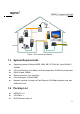
PLC Camera Powerline WiFi Extender PLC ADSL PLC FTTH PLC Figure 1 PLC network architecture 1.3 System Requirements Operating system: Windows 98SE, 2000, ME, XP 32/64 bit, Vista 32/64bit, 7 32/64bit CPU: Intel Pentium III or better, clock rate faster than 2.0GHz recommended RAM: At least 128MB Screen resolution: Any resolution Free disk space: At least 20MB Network interface: At least one Fast Ethernet (100 Mbps) network card, and a Ethernet Cord 1.
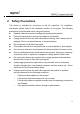
2 Safety Precautions This device is intended for connection to the AC powerline. For installation instructions, please refer to the installation section of this guide. The following precautions should be taken when using this product. Read all instructions before installing and operating this product. Follow all warnings and instructions marked on the product. Unplug the device from the wall outlet before cleaning. Use a damp cloth for cleaning. Do not use liquid cleaners or aerosol cleaners.
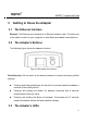
3 Getting to Know the Adapter 3.1 The Ethernet Interface Ethernet: The Ethernet port connects to an Ethernet network cable. The other end of the cable connects to your computer or other Ethernet-enabled network device. 3.2 The Adapter's Buttons The following figure shows the adapter‟s buttons. Figure 2 Side panel of the device Reset\Security: Set the status of the device members or restore the factory default settings. .
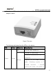
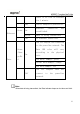
All adapter's LEDs are located on the front panel. There are 3 LEDs to indicate the adapter‟s status. Figure 3 Top view The following table describes the LEDs on the device. LED Color Behavior Description On System runs normally. System is resetting Password synchronization is in Power Green progress.
there is no link on ethernet for 1 minute. - Off Green On Ethernet - The PLC adapter is powered off. Ethernet connection has established. Blink Data is being transmitted. Off No Ethernet connection. The PLC adapter has connected to the powerline network. The Data Green /Oran ge/Re Data On LED according color to will the vary physical rate.
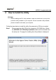
4 How to Install the Utility Note: Before installing the PLC utility software, make sure that there is no any other powerline utility installed on your computer. If there is another utility installed, please uninstall it and restart your computer. Follow the steps below to install the utility. No password or CD-Key is needed. Step 1 Please insert the utility CD into the computer‟s CD-ROM drive. Select the APPROX PLC 500 Utility Installation folder and then double-click the setup.exe.
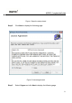
Figure 4 Open the setup wizard Step 2 Click Next to display the following page. Figure 5 License agreement Step 3 Select I Agree and click Next to display the following page.
Figure 6 Selecting the folder Step 4 Click Browse… to select the installation folder, and then click Next to continue.
Figure 7 Confirm installation Step 5 Click Next to display the following page.
Figure 8 Completing the installation Step 6 Click Close to finish the installation.
5 How to Use the Utility Click the desktop icon below to enter the configuration page. Figure 9 Desktop icon 5.1 Main Tab The Main screen provides a list of all powerline devices logically connected to the computer when the utility is running. The top panel shows the local HomePlugAV devices connected to the network interface card (NIC) of the computer. Click Connect. The utility automatically scans the powerline periodically for other HomePlugAV devices connected to it.
Figure 10 Main tab The lower panel displays all the HomePlugAV remote devices, which are discovered in the current logical network. The total number of remote devices connected in the same network is displayed above the remote device panel. Network type (Public or Private) depends on the network status of the local device. Autoscan shows whether the autoscan function is on. The following information is displayed for all the devices that appear in the lower panel.
MAC Address This column shows the MAC addresses of the remote devices. Password By default, this column is blank. You can click Enter Password to change it. The steps for setting the password of the device (required when creating a private network) are as follows: Step 1 Click the device name to select the device in the lower panel. Step 2 Click Enter Password. A dialog box appears, showing the device name and password. Figure 11.
Figure 11 Setting the device password Step 3 Click OK to verify the password. The password field accepts the device password in any case formats, with or without dash. A confirmation box appears if the password is entered correctly. If a device is not found, a message appears, providing suggestions to solve the common problems. This process might take a few seconds to get completed. Add This button is used to add a remote device to the existing network by entering the device password of the device.
Figure 12 Adding the remote device Note: The device must be in the powerline (plugged in), so that you can confirm the password and add the device to the network. If the device is not located, a warning message appears. Scan This button is used to perform an immediate search for HomePlugAV devices connected to the powerline network. By default, the utility automatically scans every a few seconds and updates the displayed information.
5.2 Privacy Tab In the Privacy screen, you can maintain security for the logical network and select the device included in the network. See Figure 13. Figure 13 Privacy tab All HomePlugAV devices are loaded using a default logical network (network name), which is normally “HomePlugAV”. In the Privacy screen, you can modify a private network by changing the network names and the passwords of the devices.
You can always reset to the HomePlugAV network (Public) by entering “HomePlugAV” as the network name or by clicking on the Use Default button. Note: If the network name changes to anything other than HomePlugAV, the network type in the main screen is displayed as Private. Set Local Device Only This button is used to change the network name and password of the local device.
5.3 Diagnostics Tab The Diagnostics screen shows the system information and history of all remote devices appeared over a period of time. See Figure 13. The Upper panel shows technical data concerning software and hardware on the host computer that are used to communicate through HomePlug on the powerline network.
Figure 14 Diagnostics tab The Lower panel displays the history of all remote devices appeared on the computer over a certain period of time. All the devices and the parameters of the devices on the powerline network are listed. Devices that are active on the current logical network show a transfer rate in the rate column. Devices on other networks, or devices that no longer exist are shown with a “?” in the rate column.
Date device last seen on the network MAC firmware version The diagnostics information displayed can be saved to a text file for later use, or be printed for reference for a technical support call. Click Delete to delete the devices which are no longer part of the network. A dialog window pops up with a confirmation message if the user wants to delete a device whose password has been entered. 5.
Preferences The lower part of the panel displays options for turning the autoscan function on or off.
6 How to Use the Reset\Security Pushbutton This chapter describes how to use the Reset\Security pushbutton to add new devices into or remove devices from a HomePlug AV logical network (AVLN). You can monitor the operation progress and results by observing the Power LED status. 6.1 Forming a HomePlug AV logical network Scenario: Devices A and B with different NMK values are connected to the same powerline. Users want to use them to form a logical network.
indicators on both devices illuminate steadily. If the connection fails, the Power indicators on both devices keep steady on, but the Data indicators on both devices are off. In that case, repeat steps 1-4. 6.2 Joining a Network Scenario: Devices A and B are located in network N. Users want to add device C (the joiner) into network N. Any devices on network N can become the „adder‟.
indicators on both devices keep steady on, but the Data indicators on both devices are off. In that case, repeat steps 1-4. 6.3 Leaving a Network Scenario: Device C is located in a network. Users want to remove device C (the „leaver‟) from its network. Figure 18 Remove a device from a network Do as follows to remove device C from network N: Step 12 Press the Reset\Security pushbutton on device C (the „leaver‟) for about 5-8 seconds. The device will reset and restart with a random NMK.
7 How to Improve the Transmission Capacity It is important to use the PLC product complying with the following "correct rules", because it can significantly improve the transmission capacity of the network. For the PLC device without female socket, it is recommended to plug the device directly into a wall socket, not to power stripe.
Appendix A Specifications Chipset Atheros AR7420 Protocol HomePlug AV, IEEE1901 Co-exists with existing HomePlug 1.
Input Rating 100-240 VAC, 50/60Hz Certifications CE, UL, FCC Part 15 Class B Green Standard RoHS Physical Dimension L×W×H: 69mm×58mm×31mm Weight 80g 28
Appendix B AVLN CCo CSMA/CA DAK DM IGMP NEK NID NMK PLC PIB STA TDMA TEI TOS VLAN Acronyms and Abbreviations AV In-home Logical Network, the AVLAN is the set of STAs that possess the same network membership key. Every AVLN is managed by a single CCo.