
User's Manual

Specifications subject to change without notice or obligation.
www.appliedwireless.com • Phone (805) 383-9600 • Fax (805) 383-9001
Revised 07/27/16
Long Range Wireless Solutions
TL900 Transceiver Module
REFERENCE DESIGNS
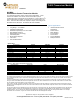
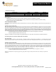
PINOUTS
_____
GROUND 1 32 NOT USED
+3.3 VOLTS OUTPUT 2 31 OUTPUT 8
+3.3 to 12 VOLTS INPUT 3 30 GROUND
UART INPUT for Transmit 4 29 OUTPUT 7
UART OUT PUT from Re ce i ve 5 28 O UT PUT 6
CTS\ OUTPUT, (SLEEPEN\ INPUT*) 6 27 OUTPUT 5
BEEP OUTPUT 7 26 RSSI\ OUT
LEARN\ INPUT, LEARN LED OUTPUT 8 25 OUTPUT 4
BEEP\, (CONFIG RESISTOR GND*) 9 24 OUTPUT 3
ACK_ENABLE\ INPUT* 10 23 OUTPUT 2
NOT USED 11 22 OUTPUT 1
INPUT 1 12 21 INPUT 8
INPUT 2 13 20 INPUT 7
GROUND 14 19 GROUND
INPUT 3 15 18 INPUT 6
INPUT 4 16 17 INPUT 5
TL900R
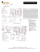
TL900R Notes
1. A 2.2k resistor between SLEEPEN
and CONFIG RESISTOR GND will
allow the unit to sleep if idle for 30
seconds.
2. A 2.2k resistor between
ACK_ENABLE and CONFIG
RESISTOR GND will allow the unit to
give an acknowledgment reply after
the receipt of an acknowledgment
request. For point-to-multipoint
applications only one acknowledgment
should be enabled.
3. The use of CONFIG RESISTOR GND
minimizes idle current for low power
sleep mode. The resistors are
sampled on power up.
4. A 2.2k resistor between DtoA_SEL
(pin 26) and
CONFIG_RESISTOR_GND will select
DtoA_OUT configuration instead of
ANALOG_IN.
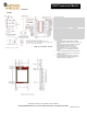
TL900R REFERENCE DESIGN
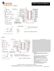
TL900R UART REFERENCE DESIGN