
User's Manual

Specifications subject to change without notice or obligation.
www.appliedwireless.com • Phone (805) 383-9600 • Fax (805) 383-9001
Revised 07/27/16
Long Range Wireless Solutions
TL900 Transceiver Module
900 MHz
Data/Remote Control Transceiver Module
Long range RF module for data or remote control applications. Three
versions are available: The remote control version has 8 inputs, 8
corresponding logic level outputs and one analog I/O. There is also an I
2
C
version with 6 inputs, 6-outputs, one analg I/O, an I
2
C master and an I
2
C
slave. There is an SPI version with 4-inputs, 4-outputs, one analog I/O an
SPI Master and an SPI slave. An Evalution kit is also available.
Features Typical Applications
Long Range – 1 to 10 Miles
8-Parallel Inputs/Outputs
Serial Data Input/Output, I
2
C / SPI / UART
High EMI/RFI Tolerance
Spread Spectrum Technology
Internal Regulator
No RF Design Required
Low Power
FCC Certified Module
Industrial Remote Control
Applications
Access Control
Meter Reading
PLC Activation
Point-to-Point
Point-to-Multipoint
Multipoint-to-Point
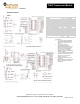
Specifications
Specifications TL900R TL900-SPI TL900-I2C
Latency See Table
Digital Inputs/Outputs 8 4 6
Analog I/O 1 1 1
Analog I/O Pin Resolution 5-Bits 10-Bits IN/ 8-Bits-OUT 10-Bits IN/ 8-Bits-OUT
Other I/O SPI Master/SPI Slave I2C Master/I2C Slave
I/O Input Pins 3.3V max 3.3V max 3.3V max
Antenna Connector RPSMA RPSMA RPSMA
Input Supply Voltage (VDC) 3.3-12 3.3-12 3.3-12
Supply Current, Receive Mode (mA) 25 25 25
Supply Current, Transmit Mode (mA) 140 140 140
Output Pin Sink/Source Current (mA) 6 / 3 6 / 3 6 / 3
Temperature Range (C) -20 to +60 -20 to +60 -20 to +60
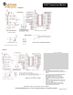
Latency vs. Range Options with Spreading Factor set at:
Spreading Factor Latency (ms) Range Bits Per Second
12 (Default Setting) 270 100% 238
11 210 80% 304
10 135 56% 474
9 82 40% 780
8 39 28% 1641
7 14 20% 4571
Notes: 1) Latency is a one-way response. 2) BPS includes two-way handshaking. 3) UART baud rate is 9600 for up to 12-byte packet input.
LEARN Procedure
The TL900 LoRa Transceiver has a Learn Mode that provides a way for two (or more) units to be able to communicate with one another. Each
unit is programmed with a unique code and the least siginificant bits of that code determine one of 32 frequencies for data communication
between units.
There is a 33rd frequency set aside for the learn process. The LEARN\ line is an input that is normally high and, when pulled low, usually
through a switch, the LEARN\ becomes a low output that can drive an LED to indicate the unit is in the learn mode. When in the learn mode,
the unit switches to the 33rd frequency in the receive mode.
If two units, #1 and #2, are placed in the learn mode, the second push of the learn button for unit #2 will cause that unit to transmit a signal
requesting an acknowledgement from the unit #1 which will contain its code. Unit #2 will then adopt the code of unit #1 and both units will exit
the learn mode.
The same procedure can be repeated for unit #1 and unit #3, then unit #1 and unit #4, etc. All units will have adopted unit #1's code and will
comprise a network. However, the acknowledgement on all but one unit will have to be disabled to avoid collisions. For one transmitter to
multiple receivers, only one receiver can have the acknowledgement enabled. It should be the one at the greatest distance. For multiple
transmitters and one receiver, only the one receiver should have the acknowledgement enabled.