
User Manual
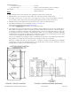

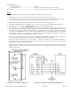
Table Of Contents
- Reader DescriptionRevision G June 09, 2006
- Parts List
- Installation Procedure
- Product Specifications
- Cable to Controller (for basic connections)
- Read Range with AWID Card (Metal-Compensated)
- Notes
- When wiring the reader, connect the black wire (ground) first, and the red wire (power) last.
- When the yellow wire is not used, the beeper remains active and under the reader’s internal control.
- The Beeper and LED lines are logic levels. Never apply power to them. They may be pulled to a low level (0 to 1.2 VDC) to enable their function, and left floating at a high level (3.6 to 5.0 VDC) when not used.
- SR-2400 readers have Wiegand-protocol electrical interface only. (There is no RS-232 interface.)
- For additional information, please visit AWID’s web site (|www.awid.com). Send all technical support questions to |support@awid.com. Call AWID at 1-800-369-5533 from 8:00 a.m. to 7:00 p.m. Eastern Time.
- FCC Compliance: This equipment has been tested and found to be in compliance with the limits for FCC part 15, Class A digital device. These limits are designed to provide reasonable protection against harmful interference when the equipment is ope
- The users are prohibited from making any change or modification to this product. Any modification to this product shall void the user’s authority to operate under FCC Part 15 Subpart A Section 15.21 regulations.
- This device complies with Part 15 of the FCC Rules. Operation is subject to the following two conditions: (1) This device may not cause harmful interference, and (2) this device must accept any interference received, including interfer
- FIGURE 1: HOLES LOCATION

SR
-
2400 Revision G Reader Installation Sheet
09 June 2006
Page 2 of 2
Operating Parameters
·
Excitation Frequency
................................
.................
125 kHz
·
Wiegand Output
..........................................................
26 bits to 50 bits (determined by code in credentials)
Certifications
................................................................
...............
UL 294 Listed; FCC Part 15 certification; Industry Can
ada; CE
Notes
1.
When wiring the reader, connect the black wire (ground) first, and the red wire (power) last.
2.
When the yellow wire is not used, the beeper remains active and under the reader’s internal control.
3.
The Beeper and LED lines are logic levels.
Ne
ver
apply power to them. They may be pulled to a low level
(0 to 1.2 VDC) to enable their function, and left floating at a high level (3.6 to 5.0 VDC) when not used.
4.
SR
-
2400 readers have Wiegand
-
protocol electrical interface only. (The
re is no RS
-
232 interface.)
5.
For additional information, please visit AWID’s web site (
www.awid.com
). Send all technical support questions to
support@awid.com. Call AWID at
1
-
80
0
-
369
-
5533
from 8:00 a.m. to 7:00 p.m. Eastern Time.
6.
FCC Compliance: This equipment has been tested and found to be in compliance with the limits for FCC part 15,
Class A digital device. These limits are designed to provide reasonable protection again
st harmful interference when
the equipment is operated in a commercial environment. This equipment generates, uses and can radiate radio frequency
energy and, if not installed and used in accordance with instruction manual, may cause harmful interferenc
e with radio
communications. Operation of this equipment in a residential area is likely to cause harmful interference in which case
the user will be required to correct the interference at his own expense.
The users are prohibited from making any change
or modification to this product. Any modification to this product
shall void the user’s authority to operate under FCC Part 15 Subpart A Section 15.21 regulations.
This device complies with Part 15 of the FCC Rules. Operation is subject to the following
two conditions:
(1) This device may not cause harmful interference, and (2) this device must accept any interference received, including
interference that may cause undesired operation.
7.
Industry Canada Compliance: Operation is subjec
t to the following two conditions: (1) This device may not cause
harmful interference, and (2) this device must accept any interference, including interference that may cause undesired
operation of the device.
FIGURE 1: HOLES LOCATION
FIGURE 2: WIRING DIAGRAM (WIEGAND)