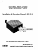
SENTINEL-PRO SP-6820 DOOR FRAME PROXIMITY READER Installation & Operation Manual 003-98-A Your best option for Proximity Access Control Last Update: February 4, 1992 WADI Applied Wireless Identifications Group, Inc.
Table of Contents 1.0 Introduction... 1.1 General Description: 1.2 Special 1.3 Suggested Applications 2.0 Principal of Operation... 3.0 3.1 Measuring Read Distance. 4.0 Preparation for Installation 4.1 Site Survey... 4.2 General Good Reader Installation Practice 4.3 Metal 4.4 General Wiring Requirements OO 4.5 Power Supply. J 4.6 Grounding. 4.7 Wiring Diagrams.. 5.0 Installation Procedure. 5.1 Parts 5.2 Installation Steps. 5.3 Verification... 7.0 Return Material Authorization (RMA) 8.0 9.
1.0 INTRODUCTION: Aw Id's Sentinel-Prof MP-8820 Reader is one of the best performing Proximity Readers in the industry. This Reader is per-compensated for taunting on metal utility box with simultaneous Gandhian and RS-232 outputs. Its primary applications are Access Control and Time & Attendance applications. 1.1 General Descriptions: « Thin-line switch plate mounting + LED visual indicator « Indoor or outdoor installation + Audible feedback 1.
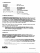
3.0 SPECIFICATIONS to +12V -l Input current... to 120 mA typical Read range: to 8 inches (20 cm) Prof-Linc-CS. .Up to 8 inches (20 cm) Transmit frequency... .125KHz (CW) Receiver -125KHz (Amplitude Modulated) .-30° C to +65° C .Dark Gray or Beige & RS-232 (Standard) (Others are available upon request) Operating temperature range. Color... Output formats 3.
+ Keep all the Reader wiring at least 12 inches (30 cm) away from all other wiring, which include but not limited to, AC power, computer data wiring, telephone wiring and wiring to electrical locking devices. * Do not install the reader within 12 inches computer CRT terminal. 4.2 General Good Reader Installation Practice * Make sure that the supply voltage of the Reader is within specification.
NOTE: WHEN USING AN EXTERNAL POWER SUPPLY, ALWAYS USE A LINEAR POWER SUPPLY, DO NOT USE SWITCHING POWER SUPPLY. 4.5 Power Supply The operating frequency of a typical switching power supply ranges from 15 KHz to 50 KHz. It will usually generate wide band switching noises plus some of its harmonics may fall on or near 125 KHz, the operating frequency of the Reader. Therefore, avoid using a switching power supply at all times. AVOID using a single power supply for Reader and the magnetic lock.
Prepare the single-gang electrical wiring box for Reader mounting. . If double-gang electrical box are used, drill through the four blind mounting holes on the four corners of the Reader. Guide the open end of the Panel's control cable through the access hole on the electrical junction box. Secure the cable by tightening the cabin clamp. Remove the Snap-On cover of the Reader (item b. of the parts list). Connect the Reader and the Panel together according to Figure 5.2-1 for Gandhian format, Figure 5.
Fig. 5.2-2 Wiring Diagram For RS-232 Output Format READER BEEPER (YELLOW) eo A CUT ya PANEL PSR + DTR CTS RTS LED DATA (WHITE) e DATA (GREEN) o HOLD (BLUE) ® LED (BROWN) TRANSMIT (VIOLET) ® RXD RECEIVE (ORANGE)® GROUND (BLACK) » TXD GROUND 5.
5.4 Mounting a. Connect the remaining wires on the Figure to the PANEL. b. Mount the Reader securely to the electrical junction box with #5-32x1 machine screw. (Item ¢ on Parts List). c. Install the Snap-On cover. 6.0 WARRANTY Aw Id's products are warranted to the original purchaser to be free of defects in material and workmanship for the life of the product. Any tampering or modification to the product will void this product warranty.
“ When troubleshooting, try to identify the source of the problem to a unit level. “Is the problem from the panel?” Or “is the problem originated from the Reader? “ Maybe the problem “is the power supply?” All Aw Id's readers will need ably a power supply and a valid card to work properly. if the reader is only connected with RED and BLACK (Ground), the reader will BEEP and momentarily turned AMBER, when a valid card is presented.