
User's Manual
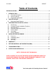

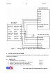
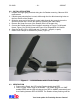
Table Of Contents

SC-2300 - 10 - 2/5/2007
Your best option for Proximity Access Control
4.2 INSTALLATION STEPS
1. Prepare the single-gang electrical wiring box for Reader mounting. Observe ADA
requirements.
2. If double-gang electrical box is used, drill through the four blind mounting holes on
the four corners of the Reader.
3. Guide the open end of the Panel’s control cable through the access hole on the
electrical junction box. Secure the cable by tightening the cable clamp.
4. Remove the Snap-On cover of the Reader (item b of the parts list)
5. Connect the Reader and the Panel together according to Figure 1 for Wiegand
format, Figure 2 for RS-232 format and Figure 3 for Wiegand/RS-232 format.
6. Setup for the RS-232 is: 9600 baud rate, 1 start bit, 1 stop bit, no parity.
7. Install Ferrite clamps as illustrated in picture (Figure 4).
Figure 4 SC-2300 Reader with 2 Ferrite Clamps
4.3 VERIFICATION
1. Power up the Panel, the LED on the Reader should show RED.
2. Place a “good” card in front of the Reader. The reader will give out “ONE”
audible BEEP and the LED will change from RED to AMBER momentarily and
then flashing between RED & GREEN. The Reader will stay flashing until the