MPR-3014WF-QB -1- Doc# 041325 SENTINEL-SENSE MPR-3014 MPR-3014WF-QB Installation & Operation Manual
MPR-3014WF-QB -2- Doc# 041325 COPYRIGHT ACKNOWLEDGEMENTS The contents of this document are the property of Applied Wireless Identifications Group, Inc. (AWID) and are copyrighted. All rights reserved. Any reproduction, in whole or in part, is strictly prohibited. For additional copies of this document please contact: AWID 18300 Sutter Blvd Morgan Hill, CA 95037 http://www.AWID.
MPR-3014WF-QB -3- Doc# 041325 This device has been designed to operate with the antennas described below, and having a maximum gain of 6 dBi. Antennas not as described or having a gain greater than 6 dB are strictly prohibited for use with this device. The required antenna impedance is 50 ohms. 1) AWID, model ANT-915CPD-A; 5.9 dBi circular polarized antenna (Patch). 2) Snyder Antenna Systems, Inc., model ANTUHF-PORT-X; 6.5 dBi Patch Antenna (Sidewinder). Note: to compromise the 6.
MPR-3014WF-QB -4- Doc# 041325 Table of Content 1. INTRODUCTION.................................................................................................................. 5 1.1. 1.2. 2. SPECIAL FEATURES ........................................................................................................... 5 MODEL NUMBER ASSIGNMENT ......................................................................................... 6 SPECIFICATIONS........................................................
MPR-3014WF-QB -5- Doc# 041325 1. INTRODUCTION AWID's Sentinel-Sense MPR-3014 WinCE bi-static reader MPR-3014WF-QB is a multiantenna Radio Frequency IDentification (RFID) reader with an on-board WinCE. Reader Versions MPR-3014WF-QB-NA (WinCE, Fixed, Quad-Ant, Mono-static & North America) I/O Interface One unique configuration for the MPR-3014WF-QB readers is the possibility of having RS-232 interface and Ethernet interface simultaneously present at the reader data input ports.
MPR-3014WF-QB -6- Doc# 041325 1.2.
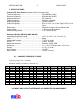
MPR-3014WF-QB -7- Doc# 041325 2. SPECIFICATIONS Common RF Specifications (North America Versions only) Transmit frequency................................................. 902-928 MHz (ASK) Receiver frequency................................................. 902-928 MHz (ASK) Hopping channels................................................... 50 Channels Channel spacing..................................................... 500 kHz or 200kHz Hopping sequence..................................................
MPR-3014WF-QB -8- Doc# 041325 2.2.1. General Purpose Input/Output Terminal block – MPR-3014WF-QB 4 inputs & 4 outputs (optically isolated) Pin # 1 2 3 4 5 Function description Output 1 Output 2 Output 3 Output 4 Output Common Pin # 6 7 8 9 10 Function description Input Common Input 4 Input 3 Input 2 Input 1 The four general-purpose inputs that use photo diodes are used to accept TTL input commands. Each input requires 15 mA and 5V to activate. The four outputs are solid state relays, with 0.
MPR-3014WF-QB -9- Doc# 041325 3. INSTALLATION PROCEDURE This section provides installation and operation information for MPR-3014WF-QB readers. 3.1. PARTS LIST Verify that all items listed below are present before starting the installation. a. Sentinel-Sense MPR-3014WF-QB b. ANT-915-CPD-A c. RTC08/16/24 d. Documentation & Demo Program CD e. 827-06W – Reader mounting bracket (Optional) f. PS12-3.3AR – 12 VDC wall plug power supply unit (Optional) Qty=1 Qty=1~4 Qty=2~8 Qty=1 3.2.
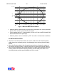
MPR-3014WF-QB - 10 - Doc# 041325 Width ( W) W (0.72R) 0 0.15 0 0.25 0.5 Distance (R) 0.75 R Figure 1 MPR-3014WF Antenna Pattern • Antenna pattern measurements represent both horizontal and vertical polarized planes of the read area transmitted by the reader. • In the drawing above, R = approximately 12 feet to 15 feet for MPR-3014WF-QB antenna with Alien free space tags. • Antenna pattern can be affected by RFI and other environmental conditions. 3.3.
MPR-3014WF-QB - 11 - Doc# 041325 4. Notes on Software Programming and System Operation 4.1. SET UP AND SYSTEM OPERATION 4.1.1. Setting Up MPR-3014WF-QB Power up with the 12-V power supply unit, connect to Network through the Ethernet port with an RJ-45 cable. 4.1.2.
MPR-3014WF-QB - 12 - Doc# 041325 O FOR DEMO SOFTWARE USERS If you are using the AWID demonstration software application which is .NET based with easy-to-follow GUI operations, simply fill in the IP address of MPR-3014WF-QB installed then click “Connect” should get you started. 5. MPR-3014WF Protocol See MPR-3014WF Protocol – 041317 6. Appendix 6.1. SAMPLE GPIO APPLICATION Shown in diagram below is an example of applying such external devices as stack lights, photo eyes, etc. to GPIO ports.