
Installation Instructions

Instructions LR-911, Part 2 14 September 2005 Page 8 of 8
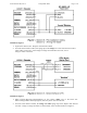
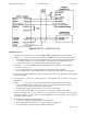
NOTES for Figure 2
1. Unused wires: Separate the unused wires (orange, violet and brown). Tape them off singly.
2. Arming: o To arm the reader permanently, tie the yellow wire to the black wire at the reader.
o To arm the reader only when an approaching vehicle is over a ground loop, ground the yellow
wire when the vehicle is over the ground loop by connecting it to the ground loop’s relay.
o To disarm the reader, let the yellow wire float (connected to nothing).
3. Data lines: o Connect the blue wire to the reader port’s “Data Common” or “Signal Return”
terminal, if there is one.
o If not, connect the blue wire to the reader port’s “Electrical Ground” terminal.
o Be sure that the green, white and blue Data wires all go to the same reader port on the panel.
4. Drain: Tie the reader’s drain wire (with clear insulation) to the cable’s shield, but do not ground
the shield anywhere.
5. Chassis ground: Connect the panel’s ground to earth ground only if listed in the panel’s
instructions.
6. Power: o Do not power the LR-911 reader from the reader port’s DC power terminal.
o Use an independent power supply for the readers – a linear regulated DC power supply,
between 7 volts, 1.5 amperes and 15 volts, 0.75 ampere.
o A typical power supply for each reader is 12 volts, 0.75 to 1.0 ampere.
o Use a separate power supply for each reader, or a central power supply for all readers.
7. Electrical grounds: Do not tie grounds for the independent power supply and the panel’s
reader port together. Connect only the reader’s black wire to the independent power supply’s
ground or negative terminal.
8. Tests: Before sealing the cable terminations --
o Test no-load voltage at the independent power supply, and
o Test voltage at the reader when it is connected to the power supply, and
o Test reader and tag operation using the LRIN installation kit.
L.H.H. 15Sep’05