
Installation Instructions

Instructions LR-911, Part 2 14 September 2005 Page 2 of 8
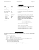
A. PRODUCTS
Reader LR-911 For WS and MT tags. (Reader does not
contain an LED.)
Mounting Bracket LRMB For LR-911 reader.
(Includes screws for nuts on reader.)
Windshield Tag WS For attachment inside windshields; passive.
Metal-Mounting Tag MT For attachment to flat surfaces including metal; passive.
Installation Kit LRIN Consists of …
Test unit SP-6820-LR Has beeper and LED; includes cable with spring clips.
Power module PS12-1A DC power supply, 12 volts, 1 ampere, linear regulated.
Test tag GMWS Windshield tag attached to 3 inch by 4 inch glass sample.
Test tag MT Metal tag for zone mapping and location testing.
Adapter cable -- 6 inches long, with 9-pin “D” female connector and
3 spring clips.
Documents -- Instructions: “Part 1. Planning the System”
“Part 2. Installing the Products”
“Part 3. Assuring Best Performance”
“LR-911 Surveillance Zone Diagram”
“GMWS – Instructions for Holding”
“Tags for Long-Range Readers – Location, Testing”
“Vehicle Mounting Recommendations for WS Tag”
“Vehicle Mounting Recommendations for MT Tag”
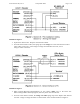
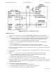
Wiring – Good Practices
Please observe these important suggestions when wiring the LR-911 reader – or any low-voltage products
or systems.
• Connect wires in this sequence:
First ...........ground connections.
Second.......general wiring – data lines, control lines.
Third..........power. (Be certain that all other wires are connected before applying power.)
• The LR-911 has, in effect, 3 separate ground connections –
black wire to the power supply’s negative,
blue wire to the panel’s data common, and
drain wire to the shield of the cable between reader and panel.
Do not connect these three wires together. Do not earth-ground any of these wires.