
User's Manual
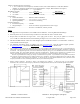
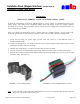
Table Of Contents
- Reader DescriptionRevision EAugust 15, 2006
- Parts List
- Installation Procedure(Installation notes for MR-1824-MC are on attached sheet.)
- Product Specifications
- Material of the mounting surface
- Cable to Controller (for basic connections)
- Read Range (Typical)MR-1824MR-1824-MC
- _
- Notes
- For suggestions on best performance, read AWID’s
- When the yellow wire is not used, the beeper rema
- Beeper, Hold, and LED lines are logic levels. Never apply power to them. They may be pulled to a low level (0 to 1.2 VDC) to enable their function, and left floating at a high level (3.6 to 5.0 VDC) when not used.
- MR-1824 and MR-1824-MC readers have both Wiegand-
- For additional information, please see AWID’s web
- FCC Compliance: This equipment has been tested and found to be in compliance with the limits for FCC part 15, Class A digital device. These limits are designed to provide reasonable protection against harmful interference when the equipment is operated
- The users are prohibited from making any change o
- Industry Canada Compliance: Operation is subject to the following two conditions: (1) This device may not cause harmful interference, and (2) this device must accept any interference, including interference that may cause undesired operation of the
- _
- Instructions

MR-1824 Revision E Reader Installation Sheet 15 August 2006 Page 3 of 3
Installation Sheet (Wiegand Interface) (Part No. 004-97-A)
Sentinel-Prox MR-1824 Reader
Instructions
INSTALLING FERRITE CLAMP ON POWER SUPPLY CABLE
To meet the requirements of the FCC, AWID supplies a “ferrite clamp” for installation on the power
supply wiring. The clamp can be installed by hand, easily and quickly, at the site, without removing
the reader or its wiring. This procedure may be used on a power supply that was installed earlier, or
on one being newly installed.
Three wires must pass through the ferrite’s channel when it is snapped closed – (a) the positive DC,
(b) the DC ground, and (c) the drain wire from the reader and the cable’s shield to earth-ground.
1. Locate the low-voltage DC power supply and the wires that connect it to the MR-1824 reader or
the MR-1824-MC reader.
2. Arrange for enough excess wire length so that the wires can loop through the ferrite clamp with two turns
of the wires inside the channel of the clamp.
3. Hold the open clamp (Figure 1) at a place where the three wires are accessible.
4. Loop the wires twice around the channel in the ferrite. Pull the wire loop tightly around the ferrite clamp.
5. Press the ferrite clamp around the wires until the latch at one end of the clamp snaps over the ears on the other
end of the clamp. (See Figure 2.)
FIGURE 3. Ferrite clamp (open) FIGURE 4. Ferrite clamp locked on 3 wires
Note
: If it is necessary to remove the ferrite clamp from the wires, insert a fingernail under the latch and lift it
off the ears. The clamp will then swing open.