
User's Manual


Page 6 12/21/2004
AWID PROPRIETARY
Passive tags are “beam powered”, which is the electromagnetic energy radiated by the
transmitter section of the reader. Upon receiving a legitimated command, the tags will
cause the matching of the tags antenna to vary from match to mismatch, thereby causing
the tags to either absorb the RF energy or to reflect the RF energy. This absorption or
reflection sequence is commanded by the tag’s internal memory and this is how the tag’s
internal data are “conveyed” to the reader. The reader in turn monitors the perturbation of
the RF energy field, and thereby receives the varying degree of signal reflected from the
tag.
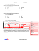
One of the unique design features for an RFID reader is that it must simultaneously
transmit a strong CW signal, while at the same time, receives a weak reflected signal
with little frequency separation. In a traditional design, such functions are implemented
through the use of a circulator. As shown in Figure 1, there is a 3-port device between
the Coupler and the band pass filter, which is called a circulator. A circulator is physically
constructed by a permanent magnet, a Y junction on a high-dielectric ferromagnetic
substrate, and a ferromagnetic enclosure to complete the flux field. A circulator permits
flow of RF energy in one direction only, e.g. from port 1 to 2, 2 to 3, and 3 to 1. When
one of the ports is terminated (matched condition), the other two are isolated in the
reverse direction. Many fixed-site RFID readers use circulators to ensure that the power
amplifier output flows from the amplifier (port 1) to the antenna (port 2), and the received
signal flows from the antenna (port 2) to the receiver (port 3). When properly matched, a
circulator can provide typically 15 to 18 dB of isolation between the power amplifier
output (port 1) and the receiver input (port 3), thereby reducing any in-band interference
from transmitter output to receiver input. MPR-2010 uses a similar circuit to accomplish
the same function, but in a much smaller physical size.
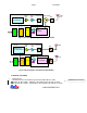
It should be noted that some fixed-site reader designs use separate transmit and receive
antennas to resolve this T/R signal isolation problem. Figure 2 is a block diagram of a
dual-antenna RFID reader. On the surface, this design has the advantage of allowing a
low-level design on the receive chain, which means lower compression point for mixers,
lower saturation point for amplifiers, and the possibility of using a front-end amplifier to
enhance receiver sensitivity. Such dual-antenna design becomes problematic in a mobile
environment, where signal strength is not easily controlled. A well-designed dual-antenna
reader can usually provide 25 to 30 dB of isolation between the two signal paths,
reducing the unwanted signal in the receive chain to –20 dBm. However, when the RFID
reader antenna is facing a tag placed on a large metallic object at a distance of 12
inches, the reflected transmitter signal at the receiver input can be as high as 13dBm,
thereby eliminating any advantage of the dual-antenna design.
In actual circuit implementation, AWID developed a proprietary circuit to duplicate the
functions of the circulator, with improved directivity and isolation.