K SERIES CHILLERS K4, K6, K9 STANDARD MODELS INSTRUCTION MANUAL Issue 10.33 Applied Thermal Control Ltd.
(Left intentionally blank)
K4, K6, K9 series chillers – Installation and Operation manual Contents 1.0 INTRODUCTION ................................................................................................................................. 3 Safety ..................................................................................................................................................... 4 1.1 WARRANTY REGISTRATION ........................................................................................................
K4, K6, K9 series chillers – Installation and Operation manual (Left intentionally blank) Issue 10.
K4, K6, K9 series chillers – Installation and Operation manual 1.0 Introduction By selecting a K series chiller you have invested in many years experience in the design and manufacture of precision temperature control instrumentation. ATC has built your K series chiller without compromise to meet the objectives of performance and reliability. Please read this manual carefully to ensure you understand the operation of the machine and how to use the unit safely and efficiently.
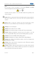
K4, K6, K9 series chillers – Installation and Operation manual Safety For your safety we draw your attention to the following Warning and Caution statements throughout the manual, identified by the symbols… and respectively. The safe operation of a K series chiller remains the responsibility of the operator at all times. Caution: Failure to comply with a Caution will invalidate product warranty and absolve ATC from any liability, howsoever caused, and could result in permanent damage to equipment.
K4, K6, K9 series chillers – Installation and Operation manual Caution: Your K series chiller is fitted with a high pressure volumetric pump, capable of supplying fluids at 150psi. Ensure that your plumbing is compatible. Caution: Filling/topping up of the tank should only be undertaken with the unit switched off, to prevent backflooding of the fluid. Caution: All connections must be made with those supplied. Caution: The high integrity refrigeration system contains no user-serviceable parts.
K4, K6, K9 series chillers – Installation and Operation manual Remove the unit from its original packaging and ensure that there is no packaging left around the cooling ducts. Please retain all packaging in the unlikely event that the chiller needs to be returned to our local representatives. 1.3 Site requirements Hard, level surface. Ideally smooth, to allow freewheeling of the castors, which are designed for indoor use. Non-condensing ambient, from +4C to +40C, ideally indoors.
K4, K6, K9 series chillers – Installation and Operation manual Outside installation. The unit is compatible with outdoor installation, provided that shelter from direct rainfall and sunlight is provided. It is strongly recommended that Hexid A4 is used to provide baseline frost protection. Plumbing to be clean and compatible with the fluid to be used. It is advisable that the minimum of right angle bends and compression fittings are used. See also section 2.0 2.
K4, K6, K9 series chillers – Installation and Operation manual on the right side of the chiller cover, when viewed from the front. Access is via the four securing screws on the cover plate. Having ensured that the system is correctly connected, with the inlets and outlets having the correct orientation relative to your application, all joints tight and leak free, and with the unit isolated from the electrical supply, prepare to fill the unit with Hexid fluid.
K4, K6, K9 series chillers – Installation and Operation manual phase components (fans, controller and solenoid), is located to the rear of the electrical box inside the unit. See Figure 1, page 11. Setting the maximum permissible fluid pressure If your chiller is fitted with a rotary vane pump, it will be fitted with a pressure control valve as standard.
K4, K6, K9 series chillers – Installation and Operation manual Adjusting fluid flow and pressure It is possible to change the operating pressure of the chiller, also using the pressure control valve, as follows: 1. With the chiller running, release the locking nut on the pressure control valve. 2. Turn the valve knob (‘A’ in Figure 2, page 11) anticlockwise to reduce the flow/pressure, clockwise to increase the flow/pressure.
K4, K6, K9 series chillers – Installation and Operation manual Figure 1: MCB locations, looking from rear of chiller 3 phase circuit breaker Single phase circuit breaker Figure 2: Pressure control valve location - viewed from above Rear panel Issue 10.
K4, K6, K9 series chillers – Installation and Operation manual 3.0 Operation K4, K6 and K9 chillers have been configured to provide temperature stability to 0.1C. K series chillers are fitted with a high performance 3 term PID controller, which is capable of controlling temperature to within 0.1C of set point. In addition, there is a high and low temperature warning via the LED on the display of the controller, which is triggered if the temperature deviates more than 10C from the set point. 3.
K4, K6, K9 series chillers – Installation and Operation manual K39 Controller error messages If the set point is moved more than 10C the alarm may be triggered. The alarm will silence as soon as the set and measured temperatures are within 10°C. It is only possible to set the temperature outside the preset values of -4C and +35C for chillers with optional high and low temperature range extensions. 4.
K4, K6, K9 series chillers – Installation and Operation manual 4.1 – Troubleshooting This section outlines common refrigeration system faults. In most cases a refrigeration service technician will have to carry out the necessary repairs as these involve specialist skills and tools. It is very important that the prime cause of the problem is identified and rectified.
K4, K6, K9 series chillers – Installation and Operation manual Symptom: Chiller too warm Cause… Check… Action… Compressor not running Loose wiring? Locate and correct cause of fault. Fuses and/or earth leakage trip OK? Check crimped terminals Phase failure of 3 phase supplies Check orientation of phases by looking at fluid flow direction.
K4, K6, K9 series chillers – Installation and Operation manual Symptom: Chiller too cold Cause… Check… Action… Thermostat Temperature and differential OK? Adjust setting to maximum level for product quality Thermostat / bulb damaged? Repair/replace Control circuit OK? Correct faulty wiring/control Equipment runs continuously Symptom: Unit cycles rapidly or shuts down after short period of operation Cause… Check… Action… Thermostat Temperature and differential OK? Adjust setting to maximum l
K4, K6, K9 series chillers – Installation and Operation manual Symptom: Other malfunction Cause… Condenser noisy or evaporator fan Check… Action… Fixing of fan to motor shaft OK? Tighten Motor bearings OK? Lubricate or replace motor Fan blade OK? Repair/replace Motor mounting bolts OK? Tighten 5.0 Warranty terms and conditions i.
K4, K6, K9 series chillers – Installation and Operation manual 5.1 Return of goods procedure If the unit is damaged during transit, or subsequently develops a fault requiring its return to ATC, the following procedure must be followed. 1. Call the ATC service point You will be issued with a Return Materials Authorisation number (‘Q number’) and a Return Machine Declaration (RMD) form by fax. A copy of the RMD form on page 23 of this manual. 2.
K4, K6, K9 series chillers – Installation and Operation manual 6.0 Dimensions and performance, K series 6.
K4, K6, K9 series chillers – Installation and Operation manual 6.
K4, K6, K9 series chillers – Installation and Operation manual 6.
K4, K6, K9 series chillers – Installation and Operation manual EC Declaration of Conformity Applied Thermal Control Ltd.
K4, K6, K9 series chillers – Installation and Operation manual In case of repair requirement, please complete both parts of the form, and fax to ATC Part 1: Returned Material Declaration Form Returns Number: Q1_ - ___ Your Name and Address: ………………………………………………… ………………………………………………… ………………………………………………… ………………………………………………… Your purchase order number: ………………………………………………… Machine part number: ………………………………………………… Machine serial number: ………………………………………………… Collection for return to ATC – plea
K4, K6, K9 series chillers – Installation and Operation manual Appendix 1: Water cooled condenser option The water-cooled condenser option is available as an alternative to the air-cooled standard version.
K4, K6, K9 series chillers – Installation and Operation manual Appendix 2: Integral deionising cartridge option If your K series chiller is supplied with the integral deionising cartridge, it is very important that this cartridge is replaced every three months, or when the cartridge media in the appropriate window turns from blue to brown, whichever is the sooner. The only approved replacement cartridge is order code WA012, available from ATC or from our authorised distributors. Issue 10.
K4, K6, K9 series chillers – Installation and Operation manual (Left intentionally blank) Issue 10.
K4, K6, K9 series chillers – Installation and Operation manual Index RMD form ............................................... 18, 23 C controller, PID .................................................... 12 error messages .............................................. 13 S set point .................................... See PID controller E T electrical supply ................................................... 6 temperature stability .........................................................