
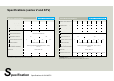
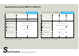
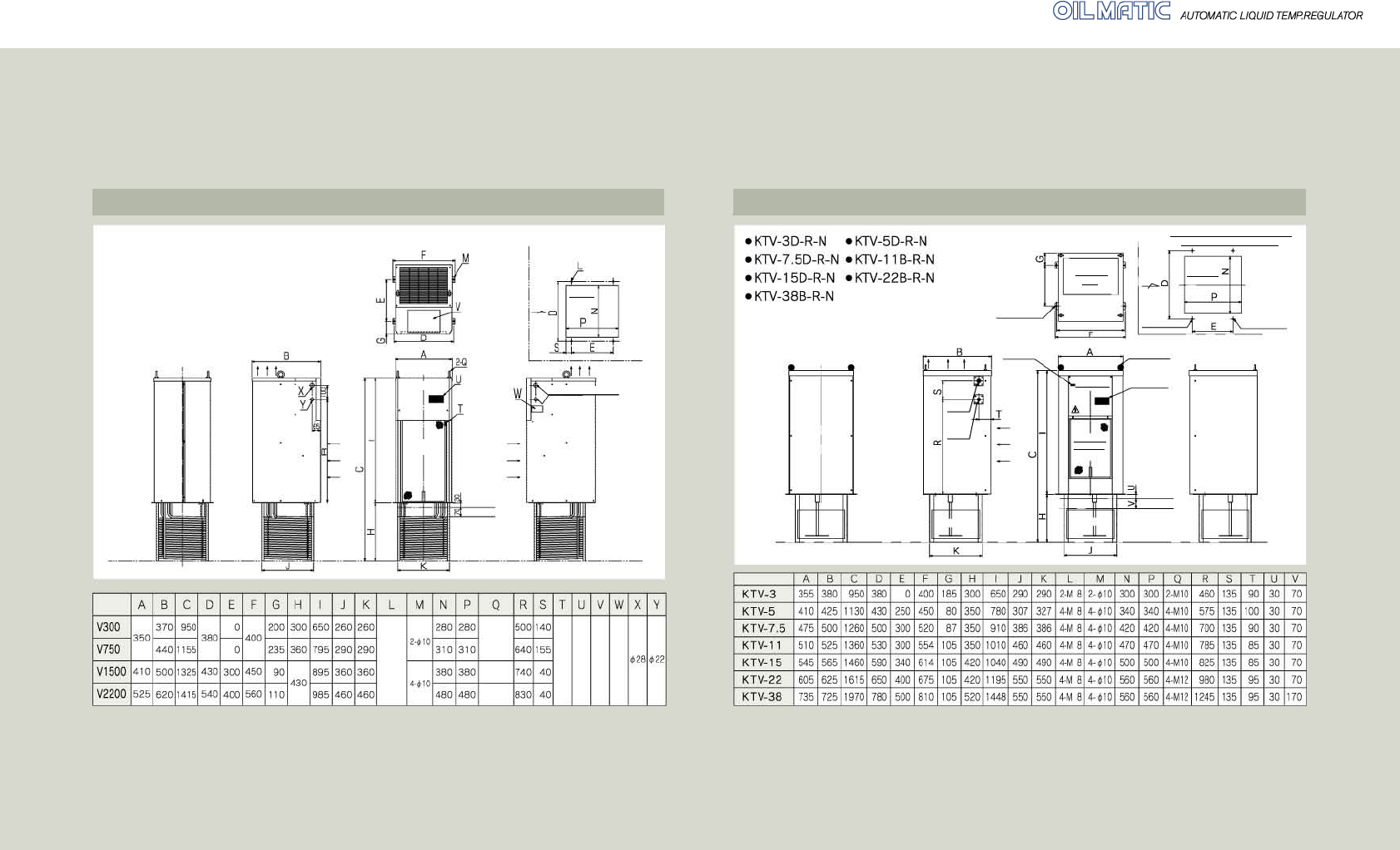
Specifications
26
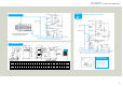
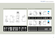
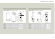
Series V dimensions Series KTV dimensions
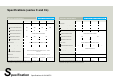
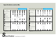
Size list
Exhaust air
Intake air
Control box
Intake vent
(with filter)
M10
Eyenut
Size list
M12
Eyebolt
M16
Eyebolt
2-
Φ10
or
tap M8
Room temperature sensor
Control panel
Caution plate
Serial No. plate
Intake air
Exhaust air
Grommet with film
* The dimension E is not applicable to models
V300 and V750 as they have only one
installation hole each on both sides. Instead,
dimension G is applied to them.
Machining dimension diagram
of main unit attaching portion
Opening
Highest liquid level
Lowest liquid level
Operating
side
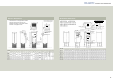
Exhaust air
Intake air
Control box
Intake vent
(with filter)
Exhaust
vent
Power
supply
hole
Φ28
Signal
hole
Φ22
Room temperature
detection sensor
Installation
pitch E
Installation hole M
Opening
Operating
side
4-Φ10
or tap M8
Fixing screw
L
Q Eyebolt
Highest liquid
level
Lowest liquid level
Control
panel
Machining dimension diagram of
main unit attaching portion
Installation
pitch D