
Specifications
14
Series
C
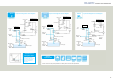
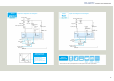
Liquid and refrigerant circuit diagram
Pressure switch
(GPS)
Condenser
Refrigerant circuit
Drier
Receiver tank
Fan motor
(M21)
Sight glass
Pulse
bypass
valve
Pulse
expansion
valve
Inverter
compressor (M2)
Liquid circuit
Discharge
port
OUT
Drain port
DRAIN
Liquid
circulating
direction
Cooler
Service valve
Sensor (TH1)
Trochoid gear pump motor (M1)
Relief valve
Oil returning
port
IN
Drain port
DRAIN
Suction filter
Liquid
temperature
sensor
Oil filler
port
Liquid level gauge
Cooling
capacity
Frequency
The twin-pulse valve control
enables a high-precision
temperature control of ±0.1°C
at low load and significant
reduction in temperature
setting time.
Control area of
twin-pulse valve
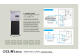
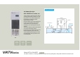
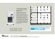
Series
CL
Liquid and refrigerant circuit diagram
Pressure switch
(GPS)
Condenser
Refrigerant circuit
Drier
Receiver tank
Fan motor
(M21)
Sight glass
Pulse
bypass
valve
Liquid circuit
Discharge
port
OUT
Drain port
DRAIN
Liquid
circulating
direction
Cooler
Service valve
Sensor
(TH1)
Trochoid gear pump motor (M1)
Relief valve
Oil returning
port
IN
Drain port
DRAIN
Suction filter
Liquid
temperature
sensor
Liquid level gauge
Capillary
tube
Compressor (M2)
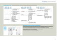
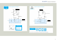
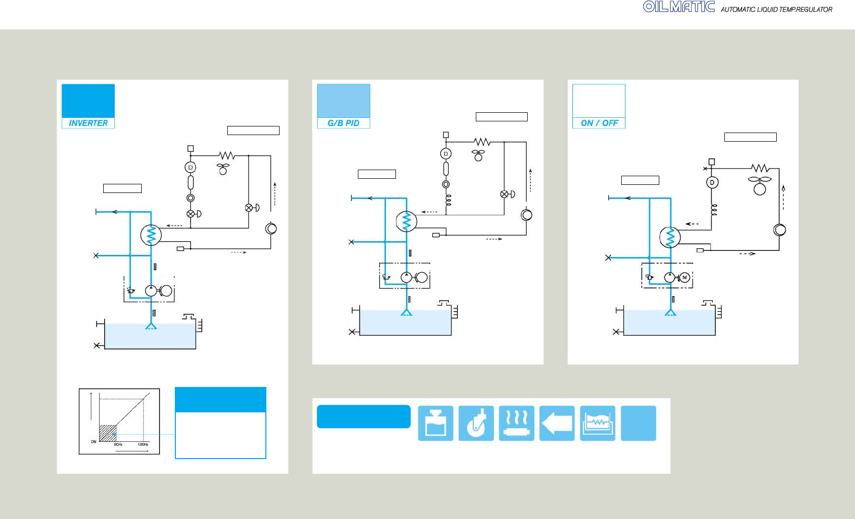
Series
ML
Liquid and refrigerant circuit diagram
Pressure switch
(GPS)
Condenser
Refrigerant circuit
Drier
Fan motor
Liquid circuit
Discharge
port
OUT
Drain port
DRAIN
Liquid
circulating
direction
Cooler
Service valve
Trochoid gear pump motor
Relief valve
Oil returning
port
IN
Drain port
DRAIN
S
uction filter
Liquid
temperature
sensor
Liquid level gauge
Capillary tube or
expansion valve
Compressor
Refrigerant
circulating
direction
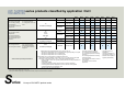
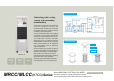
With reservoir
tank
With casters
With heater
Tropical
(passing)
treatment
Water-cooled
condenser
specifications
Specifications
complying with
various standards
Tropical
band
Standard-
compliant
Options
implemented
* Please consult us for other special specifications. For details, please contact our sales representatives.
Oil filler
port
Oil filler
port