Putting together Photograph provided by Kikuchi Seisakusho Co., Ltd.
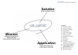
Solution Solves customers’ needs contents 03 OIL MATIC’s mission 05 OIL MATIC’ solutions 07 OIL MATIC applications 09 Product lineup 11 Product series lineup Mission 13 Series C, CL and ML 15 Series V and KTV Supports development of higher-speed and higher-precision machine tools 17 Series MRCC and MLCC 19 Series W 21 Specifications 29 Controllers Application Responds to needs from a wide range of work fields 31 Comparison of liquid temperature control methods 32 Cooling capacity diagrams 34 Cooling
“Pioneer spirit” × “Craftsmanship” OIL MATIC is an automatic liquid temperature regulator that controls temperature of any liquid used in machine tools, semiconductor-manufacturing equipment and various industrial machines with high precision. By minimizing “heat problems,” represented by thermal displacement, with OIL MATIC designed and fabricated according to machine/equipment characteristics, we maximize the machine/equipment performance and enhance the added value of workpieces.
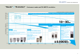
“Needs” × “Evolution” Customers’ needs and OIL MATIC’s evolution Liquid temperature fluctuation Working accuracy * The graph was illustrated in consideration of market trends.
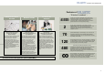
“Customers’ needs” × “Products” Customers’ needs SALES SECTION R&D DIVISION Provides best proposals based on rich experience in fields A core division for high-level product development This section handles heat-related problems that machine tool manufacturers, semiconductor-manufacturing equipment manufacturers and industrial machine manufacturers, who are our major customers, as well as users of their machines are facing and proposes the best specifications for these customers.
Features of - “6 kinds of numbers” DESIGN & TECHNICAL SECTION MANUFACTURING AFTER-SALES SERVICES ±0.00055 2 Applying design techniques focusing on customers beyond drawings Produces products with diverse specifications in short lead times Handles from maintenance and part supply to quality improvement This section reflects customers’ needs for accuracy range of temperature, control methods, etc.
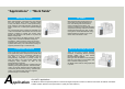
“Applications” × “Work fields” Machining centers NC lathes Major heat-generating components are main bearings and main spindle drive motors (including built-in motors). OIL MATIC is used for “main spindle cooling,” which indirectly cools heat-generating components by flowing coolant into a coolant jacket (heat-exchanging part).
NC lathes Semiconductor manufacturing equipment Major heat-generating components are a chuck head, which grips workpieces and tools, main bearings for grinding wheel spindle head and drive motors. It is common to “indirectly cool” the heat-generating components by flowing coolant into a coolant jacket (heat exchanging part).
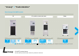
“Lineup” × “Customization” Basic lineup of OIL MATIC models Oil Oil, soluble coolant and water Circulation (closed) type Open type Circulation (closed) type Series Series Series Series Series Series C CL ML V KTV MRCC Inverter control method L ineup Water Gas bypass PID control method Series MLCC (KTCG) Circulation (closed) type Series W ON-OFF control method *For details, please refer to “Comparison of liquid temperature control methods” on page 31.
Custom-made according to application Application Required accuracy Liquid temperature control method Other customer needs OIL MATIC can control temperature of various types of liquid, not limited to oil, for machine tools and industrial machines. We develop, design and manufacture products with exclusive specifications according to application, cooling spots and required accuracy. We propose a product which reflects from liquid temperature control methods (which are the know-how of Kanto Seiki Co., Ltd.
-series products classified by application Application For cooling main spindle For controlling operating oil temperature For controlling lubricant oil temperature For cooling ball screws For cooling linear motor / DD motor Liquid used* Oil Control method Series C Inverter control Series CL Gas bypass PID control Circulation (closed) type Oil Water Coolant Open type For cooling linear motor / DD motor for semiconductor manufacturing equipment For physical and chemical equipment Model 03
About model codes * We offer other models in addition to those shown below according to your specifications. Please contact us for details. ① Series (model) name........ C: Forced circulation-type inverter PID control model V: Forced vortex-type inverter PID control model CL: Forced circulation-type gas bypass PID control model W: Forced water circulation-type inverter PID control model ② Nominal chiller capacity .... 175 : 0.17 (kW) 300 : 0.3 (kW) 750 : 0.75 (kW) 1100 : 1.1 (kW) 1500 : 1.5 (kW) 2200 : 2.
Product specifications Pressure switch (GPS) Condenser Drier Receiver tank A “standard” model supporting high precision of every machine tool Cooler Pulse expansion valve Service valve Trochoid gear pump motor Cools main spindle of machine tools, etc. Sensor Reservoir tank Product specifications OIL MATIC Condenser Cooler For temperature control of main spindle cooling oil, operating oil and hollow ball screws of machine tools, we have a lineup of three control methods according to accuracy.
Series Liquid and refrigerant circuit diagram C Series Liquid and refrigerant circuit diagram CL Condenser Drier Receiver tank Discharge port OUT Liquid circulating direction Cooler Receiver tank Liquid circuit Fan motor (M21) Sight glass Pulse bypass valve Pulse expansion valve Discharge port OUT Inverter compressor (M2) Liquid circulating direction Pressure switch (GPS) Condenser Fan motor (M21) Sight glass Capillary tube Cooler Pulse bypass valve Drier Liquid circuit Discharge port
Product specifications An immersion-type OIL MATIC for coolant, etc. These models are developed with an idea of controlling temperature of coolant, etc. with high precision. The models exchange heat by immersing a cooling coil made of stainless steel into a tank. We have a lineup of two control methods, an inverter control method and an ON-OFF control method. You can choose one according to your machining work and tank capacity.
Series Liquid and refrigerant circuit diagram Series V Liquid and refrigerant circuit diagram KTV Refrigerant circuit Pressure switch (GPS) Refrigerant circuit Condenser Condenser Drier Drier Receiver tank Fan motor (M21) Sight glass Refrigerant circulating direction Fan motor Pulse bypass valve Pulse expansion valve Capillary tube Inverter compressor (M2) Stirring motor (M1) Compressor Stirring motor Service valve Service valve Liquid circuit Liquid circuit Cooler Liquid circulating dire
Product specifications Maintaining stable cooling capacity with outstanding maintainability MRCC-07-N Cools grinding fluid Cools cutting fluid Others These series are useful when a coolant tank is too low to immerse a coil into it. The coolant tank and OIL MATIC are connected using IN/OUT pipes and coolant is forcedly circulated to control temperature. You can install these models to your existing coolant tank, or we can design and fabricate a model with “coolant pump function” for you.
Liquid and refrigerant circuit diagram Series Series Liquid and refrigerant circuit diagram MLCC MRCC (KTCG) Pressure switch Condenser Pressure switch Condenser Drier Drier Fan motor Sight glass Sight glass Pulse bypass valve Pulse expansion valve *Optional Fan motor Capillary tube Compressor Compressor *Optional Switch for preventing heating of heater without fluid Switch for preventing heating of heater without fluid Service valve Service valve Cooler Cooler Heater Heater Sensor O
Model Effective cooling capacity (W) Nominal chiller capacity (W) Controlling a wide range of “water” temperature with high precision Refrigerant used These models adopting inverter control method are used for high-precision temperature control of “water” used by built-in motors and linear motors of main spindle head, semiconductor-manufacturing equipment and various industrial machines.
Product specifications Series Condenser Pressure switch Outlet sensor Fixed aperture Liquid and refrigerant circuit diagram W Drier Fan motor Pulse bypass valve Sight glass Pressure switch Pulse expansion valve Cooler Drier Inverter compressor Service valve Inlet sensor Discharge port Temperature switch Fixed aperture Inverter compressor Service valve *Optional Temperature switch Inlet sensor Level switch Control box Grommet with film Room temperature sensor Water pump Top Water inl
Specifications (series C and CL) Series C specifications Inverter control method C 300 C 750 C 500 C 2200 Effective cooling capacity (W) 0-2000W 0-4000W 0-6000W 0-8000W Nominal chiller capacity (W) 300W or equivalent 750W or equivalent 1500W or equivalent 2200W or equivalent Model Refrigerant used Amount of refrigerant filled (g) 360 520 Rated output of fan motor (W) 25 60 Heating exchange method Flow rate (L/M) (50/60Hz) 12/14.4 24/28.
Series C dimensions Series CL dimensions Exhaust air Top Exhaust air Drain port Exhaust vent Intake air Intake air Control box Intake vent (with filter) Exhaust air Exhaust air Control box Grommet with film Size list CL-175 Intake air Within 25 B C D E F G H I J K L M N O P Q R S T U V Room Hanging Control Serial No. Φ28 Φ22 300 508 485 242 451 280 506 165 100 105 100 Rc1/2 Rc1/2 330 100 38.
Specifications (series ML) Series ML (without tank) specifications Model Effective cooling capacity (W) (50/60Hz) Nominal chiller capacity (W) ON-OFF control method MLSA-03 MLHA-03 MLLA-03 MLSA-05 MLHA-05 MLLA-05 MLSA-07 MLHA-07 MLLA-07 MLSA-11 MLHA-11 MLLA-11 MLSA-15 MLHA-15 MLLA-15 MLSA-22 MLHA-22 MLLA-22 MLSA-38 MLHA-38 MLLA-38 1160/1390 1450/1740 2900/3480 3720/4460 4830/5810 7260/8720 12200/14650 300 500 750 1100 1500 2200 3750 Refrigerant used 4200 Condenser Refrigerant use
Series MLSA, MLHA and MLLA (without tank) dimensions Series MLSB (with tank) dimensions 2-Q Eyebolt Exhaust air Exhaust air Power supply hole Φ28 Control box Power supply hole Φ28 Control box Signal hole Φ22 Signal hole Φ22 Room temperature detection sensor Intake air Intake air Room temperature detection sensor Outlet P Intake vent (with filter) Inlet N Intake vent (with filter) Inlet N Installation hole M Outlet P Installation pitch E Installation pitch D Installation pitch E Instal
Specifications (series V and KTV) Series V specifications Model Effective cooling capacity (W) Nominal chiller capacity (W) Inverter control method V 300 V 750 0-1600 0-4000 300 450 Refrigerant used Amount of refrigerant filled (g) 460 620 0-6000 0-8000 700 1100 25 780 60 1380 (50/60Hz) Nominal chiller capacity (W) KTV-3 KTV-5 KTV-7.
Series V dimensions Series KTV dimensions * The dimension E is not applicable to models V300 and V750 as they have only one installation hole each on both sides. Instead, dimension G is applied to them.
Specifications (series MRCC and MLCC) Series MRCC specifications Model Inverter control method MRCC-07 Effective cooling capacity (W) Nominal chiller capacity (W) MRCC-15 0-4000 0-6000 450 700 Refrigerant used Amount of refrigerant filled (g) 1130 2150 Rated output of fan motor (W) (50/60Hz) Nominal chiller capacity (W) Amount of refrigerant filled (g) Rated output of fan motor (W) 60 Shell and tube Heating exchange method Constant-flow forced circulation Heating exchange method RC3/4×RC3/
Series MRCC/MLCC dimensions T Eyebolt Exhaust air Control panel Power supply hole R Control box Room temperature sensor Intake air Signal hole S Intake vent (with filter) Top Drain port Inlet P Exhaust vent Outlet Q Drain port Installation pitch E Installation hole O Installation pitch D Size list 4-14×20 Elongate hole RC3/4 Socket RC3/4 Socket RC3/4 Socket RC3/4 Socket 4-14×20 Elongate hole RC3/4 Socket RC3/4 Socket 4-14×20 Elongate hole RC3/4 Socket RC3/4 Socket RC3/4 Socket RC3/4 Soc
Controller (series C, CL, V and MR) RUN lamp Turns on during operation (Turns off at alarm) High-precision temperature control at ±0.1°C (in stable heat-load state) Parameter indicating LED Data indicating LED A unique temperature control technology responds to a wide range of heat load fluctuation from no load to maximum load. Variable control of cooling capacity allows high-precision temperature control.
Controller (series ML and KTV) RUN lamp Turns on during operation (Turns off at alarm) A variety of alarm indication/output functions Digital temperature control Parameter indicating LED Temperature setting resolution: Switchable between 1°C and 0.1°C Range of temperature setting: Constant type 5.0-45.0°C Reference temperature follow-up type -9.9 to +9.
Inverter control method The inverter control is Kanto Seiki’s unique control method (patented) that uses a combination of “variable frequency control” of inverter chiller, “refrigerant flow control” of pulse expansion valve, and “cooling capacity switching control” by gas bypass expansion valve.
-05 cooling capacity diagram Oil temperature = Ambient temperature + 5°C Oil temperature = Ambient temperature Oil temperature = Ambient temperature – 5°C · · · Cooling capacity Cooling capacity -03 (CL300) cooling capacity diagram Operating conditions Oil to use: ················ VG2 Power frequency: ···· 50Hz Oil temperature: ····· Return oil temperature · · · Ambient temperature Operating conditions Oil to use: ················ VG2 Power frequency: ···· 50Hz Oil temperature: ······ Retur
-22 cooling capacity diagram Cooling capacity Oil temperature = Ambient temperature + 5°C Oil temperature = Ambient temperature Oil temperature = Ambient temperature – 5°C · · · Cooling capacity -15 cooling capacity diagram Oil temperature = Ambient temperature + 5°C Oil temperature = Ambient temperature Oil temperature = Ambient temperature – 5°C Operating conditions Oil to use: ················ VG2 Power frequency: ···· 50Hz Oil temperature: ····· Return oil temperature Ambient temperature
- 07 cooling capacity diagram - 750 cooling capacity diagram ② Oil temperature = Ambient temperature + 5°C ① Oil temperature = Ambient temperature ③ Oil temperature = Ambient temperature – 5°C Cooling capacity Cooling capacity - 03 cooling capacity diagram - 300 cooling capacity diagram · · · - 15 cooling capacity diagram - 1500 cooling capacity diagram -22 cooling capacity diagram - 2200 cooling capacity diagram Cooling capacity Ambient temperature Cooling capacity Ambient temp
For selecting a model, please contact us after you fill out the following OIL MATIC selection survey form. OIL MATIC selection survey form Temperature increase measurement Machine name Time Liquid name Liquid manufacturer Room temperature 0 min Liquid type (operating oil, cutting oil, lubricant oil, etc.
Precautions for transporting and moving OIL MATIC (1) When moving OIL MATIC using its hanging hooks, take a reliable method to keep the main unit balance stable during movement. (2) When using a forklift to move OIL MATIC in such a case that the main unit is heavy or difficult to be lifted using the hooks, pay due attention to safety and insert forklift forks deeply under the main unit until they come out of it to move the machine in stable condition.
About range of use Transportation method Series C, CL and ML Series V, KTV, MRCC and MLCC Room temperature (°C) Room temperature (°C) Since OIL MATIC uses a built-in chiller for cooling the liquid, there are limitations to the range of ambient temperature and oil temperature that can be used. Please use the machine within the range shown in the following diagrams.
Power connection About water-cooled condenser Power capacity Determine the power capacity with reference to specification lists and wiring diagrams. (Be sure to install a Molded Case Circuit Breaker (MCCB) suitable for the capacity at the main power supply.) Rotation direction OIL MATIC needs to be connected to the power supply such that an oil pump and a fan motor in OIL MATIC make positive rotation.
KANTO SEIKI CO., LTD. Headquarters refrigeration factory Eda refrigeration factory OIL MATIC Search 2-1-10, Owatari-machi, Maebashi-shi, Gunma 371-0854, Japan Direct phone number to sales office TEL 027(251)5585 FAX 027(251)0924 456, Eda-machi, Maebashi-shi, Gunma 371-0836, Japan TEL027(254)4543 FAX 027(254)4549 E-mail sales@kantoseiki.co.jp This leaflet is printed with environmentally friendly soy ink.