
User's Manual

APPLIED TECHNOLOGY SOLUTIONS, INC.
DOCUMENT: fcc1250MAN.wpd ISSUED:jan99 REVISED: (ORIGINAL) PAGE: 7
SECTION FOUR
THEORY OF OPERATION
4.0 GENERAL
The Series 1250 devices are miniaturized, transmit-only devices. They use spread spectrum modulation and low
power output to provide LPI/LPD characteristics. The devices were designed for body worn applications but may also be
planted or hidden in other objects. The devices can be equipped with a power converters allowing the use of alternative
power sources, such as a high capacity battery or DC automobile power, for long duration, fixed location surveillance
applications.
The standard antennas for the units are miniature designs that snap into the RF output connectors. These antennas
were custom designed for use with the transmitters. For special applications, the standard antenna can be replaced with a
user supplied antenna having better directional characteristics.
4.1 FUNCTIONAL DESCRIPTION
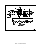
Figure 4-1 shows the block diagram of the Series 1250 transmitters. Each of the three transmitters (Models 1251,
1252 and 1253) have the same block diagram.
4.1.1 Audio/Digital Section
The Series 1250 is equipped with an internal microphone. It is supplied with an external shorting plug that
connects the internal microphone to the microphone pre-amplifier, and at the same time connects the battery to the power
supply. Whenever the shorting plug is installed, the Series 1250 transmits continuously, using the internal microphone. To
use an external microphone, the shorting plug can be replaced with a compatible microphone connected by a cable to the
Series 1250. The cable plug then makes the connection between the battery and the power supply in the Series 1250, and
connects the external microphone to the microphone pre-amplifier input. The internal microphone is not used in this
application. DC Power for the external microphone is available at the microphone connector via the connection to the DC
power input in the Series 1250.
The microphone pre-amplifier section includes an audio AGC (Automatic Gain Control) function that produces
a constant audio signal level for the CVSD (Continuously Variable Slope Delta-modulation) encoder. A lowpass filter is
used between the pre-amplifier and the CVSD encoder, to limit the audio bandwidth to the encoder to prevent aliasing.
CVSD encoding converts the analog audio into a serial data stream. The bit rate of this data stream is set by the
CVSD clock signal.
Once the audio signal is digitized by the CVSD encoder, the FPGA (Field Programmable Gate Array) handles the
processing of this signal. The FPGA performs all of the digital data processing in the Series 1250. Figure 4-1 also details
the major functional sections in the FPGA.
Serial data from the encoder is combined with a pseudo-random key stream in the data scrambler. The key stream
is generated from the scrambler key that is stored in the key memory. The scrambler key manager reads the status of the key
select switch, and reads the appropriate key from the key memory, and sends it to the data scrambler. Programming access
to the key memory is provided through the Key Loader input, which connects to the Series 1250-3 Key Loader Adapter.
Once the data stream from the CVSD encoder is scrambled, it is ready to be spread spectrum modulated. The PN
(Pseudo-Noise) sequence generator produces a long digital sequence, at a clock rate that is much greater than the signal from
the data scrambler. This signal is combined with data scrambler signal by the spread spectrum modulator. This produces