
User Manual


APPLIED TECHNOLOGY SOLUTIONS, INC.
Document: FCC1225manual.wpd issued: jan99 revised:(original) page: 3
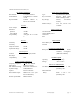
1.2 CONTROLS, INDICATORS, USER I/O
This section describes the user interfaces and indicators provided by the Model 1225 Hand Held
Transceiver.
USER CONTROLS
VOLUME Dual function rotary switch. It is the power on/off switch plus volume control
CHAN The channels are A, B and R where R refers to repeater operation.
CODE A two position switch allowing selection of either the common (C) or private (P) code.
PTT A momentary push button switch that places the Model 1225 in the transmit mode.
STATUS INDICATORS
PWR Green, multi-function LED. Steady illumination indicates that power is on and battery
condition is normal. Blinking LED indicates that the battery voltage is low and
approximately 180 minutes of receive or 15 minutes of transmit operation remain from
the time the light starts blinking.
TX Red LED, when illuminated, indicates that unit is in transmit mode.
USER CONNECTIONS
Key Loader A rear panel connector accessed by sliding the door. Connecting the Model 1260 Key
Loader to this port, privacy codes can be downloaded from the loading device to the
Model 1225 where they are stored in non-volatile memory. Operating power for the
Model 1260 is supplied from this connector.
Mic Side panel, 4 pin microphone connector. Accepts the standard Model 1230-04
Surveillance Micphone/Earpiece Assembly.
CONNECTOR SPECIFICATIONS
Microphone: Hirose HR10A-7P-4P
Antenna: SMA Female
Key Loader: ATS Model 1230-03 Adapter Cable