
Installation manual


6
The first system to understand is the Flame
Safety Control. The FSC is there only to monitor
the flame NOT to control temperature. The FSC
uses an ultraviolet (UV) sensor mounted on top of
the burner assembly to view the flame in the
burner. The FSC is also wired into an airflow
switch, which tells it whether there is proper airflow
through the unit (not just any airflow, but proper
airflow). The FSC controls the opening of the
redundant solenoid gas valves and the operation
of the spark ignitor to initiate a pilot flame upon
start-up. When there is a call for heat, the OPR
CTRL light will turn on indicating that the unit has
power. Next, the airflow light will come on if there is
proper airflow through the unit. Third, the unit will
pause ten (10) seconds to purge any gasses or
combustible vapors before attempting flame
ignition. Then, there is a Pilot Trial for Ignition
(PTFI) and the PTFI light comes on. During PTFI,
the FSC opens the redundant gas valves and
allows gas to bypass to the modulating valve (part
of the Maxitrol system). The Maxitrol valve is not
yet energized, so there is a minimal amount of gas
passing through it (called “low fire”). At the same
moment, the spark igniter is started, causing the
spark plug in the burner to ignite the gas. This
results in a low fire or pilot flame. When the UV
sensor detects the flame it turns on the flame light,
turns off the PTFI light, and powers the modulating
gas system. This is the normal operating mode.
The FSC continues to monitor the flame and
airflow.
The airflow switch is a single pole double throw
(one common contact, one normally open contact,
and one normally closed contact) switch that is
“switched” by air pressure. There are two
opposing airflow tubes in the heater, located near
the burner and profile plate assembly (profile
plates surround the burner and channel air into the
burner section). With the differential pressure
created in the airflow switch by suction on one
tube and velocity pressure on the other, the switch
will change state, indicating airflow. In the case of
clogged filters or a blocked intake, a differential
pressure is not achieved, not allowing the airflow
switch to close. With high static pressure or lack of
blower movement, no suction is placed on the
rearward-facing port and a differential pressure is
again not achieved. The airflow switch may need to
be adjusted for different pressures that occur at
different CFM’s.
The other system, the Maxitrol modulating gas
system, consists of a temperature selector dial, a
discharge air sensor, an amplifier, and a modulating
gas valve. The two types of Maxitrol systems found on
these units are the Maxitrol 14 and the Maxitrol 44.
The Maxitrol 14 utilizes a discharge air sensor and
modulates the discharge air to the selected
temperature on the temperature selector dial. The
Maxitrol 44 utilizes a room temperature sensor as well
as a discharge air sensor in order to control the room
temperature. The modulating gas valve controls the
amount of gas to the burner based on the temperature
rise needed. When the modulating gas valve is all the
way open and achieving the maximum BTU’s and
temperature rise of the unit, it is called “high fire”.
One back up safety device is the high temperature
limit switch. This switch is a mechanical thermostat
that measures the temperature inside the unit directly
above the burner. If the factory set temperature is
exceeded, it will shut down the power to the FSC. This
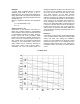
requires a manual reset. The pre-set temperature that
the factory uses is based on the temperature above
the burner when the outlet temperature is 185° F. The
settings are as follows:
Airflow Switch With Cover Removed
Maxitrol 14 Amplifier