Direct Fired Gas Heated Make Up Air Unit Operation/Installation Manual WARNING! Improper installation, adjustment, alteration, service or maintenance can cause property damage, injury or death. Read the installation, operating and maintenance instructions thoroughly before installing or servicing this equipment. FOR YOUR SAFETY If you smell gas: 1. Open windows. 2. Don’t touch electrical switches. 3. Extinguish any open flame. 4. Immediately call your gas supplier.
CONTENTS I. GENERAL INFORMATION · · · · · · · · · · · · · · · · · · · · · · · · · · 2 Receiving Equipment Direct Fired Heating II. INTRODUCTION AND OVERVIEW · · · · · · · · · · · · · · · · · · · · · · 3 III. APPLICATIONS · · · · · · · · · · · · · · · · · · · · · · · · · · · · · · · · 3 IV. THEORY · · · · · · · · · · · · · · · · · · · · · · · · · · · · · · · · · · · · 3 Temperature vs. Heat Static Pressure vs. Horsepower Gas Flow V.
installation. Direct fired heaters are designed to operate in a fresh flowing air stream. If the airflow stops or is different from the factory settings, the unit will shut down or perform below its design capability. It is important to follow the installation and start-up procedures to maximize the heater’s performance. The manufacturer has designed a unit that is easy to install, start up and service. If you have any questions, call the Service Department at 1-800-334-9256. II.
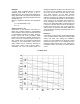
Example 1 A heater rated at 200,000 BTU’s is currently supplying 3000 CFM of air with a 62° F temperature rise. The heater needs adjustment to supply 4500 CFM of air. What is the temperature rise for this heater (assuming 200,000 maximum available BTU’s)? Using the equation to determine the temperature rise: ∆ T = 200,000/(4500 x 1.08) ∆ T = 41° Static Pressure vs. HP Construction of the ductwork connected to a heater unit is another element in understanding heater operation.
First we can determine what size motor and what This is important because the incoming gas pressure blower RPM has been set by the factory based on is often measured when the heater is not running. the initial static pressure numbers. By looking on Even though the line may appear to have the the 15” Blower Curve, we pick the intersection of appropriate pressure, the pressure will drop when the 0.125” (from the left axis) and 4000 CFM (from the heater is operating.
The first system to understand is the Flame Safety Control. The FSC is there only to monitor the flame NOT to control temperature. The FSC uses an ultraviolet (UV) sensor mounted on top of the burner assembly to view the flame in the burner. The FSC is also wired into an airflow switch, which tells it whether there is proper airflow through the unit (not just any airflow, but proper airflow).
ALL HEATERS BY THIS MANUFACTURER HAVE REDUNDANT GAS VALVES. Heaters set for less than 700,000 BTU’s use a combination gas valve. The combination gas valve has redundant solenoids and a regulator built into one body. Larger heaters use a regulator and two separate solenoid valves. The redundant gas valves shut gas flow off to the burner in case of a malfunction, no call for heat, or power outage. They are normally closed, and are energized by the Fireye FSC.
VI. HEATER COMPONENTS 2 9 7 1 4 10 8 5 11 3 12 6 15 13 14 1. Freeze-Stat Timer (Optional) Allows heater to run long enough so that it won’t shut off before reaching operating temperature. Must be used with the thermostat below. The settings should be on the yellow scale: Time sector - 30m Time value - 10m Red Switch to Right 2. Freeze-Stat Thermostat (Optional) This turns the heater off if the discharge air temperature falls below the set point. The recommended set point is 40 deg.
VII. HEATER INSTALLATION PROCEDURE NOTICE! Refer to the heater rating plate for determining the minimum gas supply pressure for obtaining the maximum gas capacity for which this heater is specified. When separate technicians perform these installations, please leave this manual for the next technician to perform their installation. When the final start-up is completed, you must return the Warranty form to activate the warranty.
of the heater is free of loose debris or shipping materials. Verify that the blower is rotating in the right direction. For 3 Phase motors, interchange any two leads to reverse rotation. For single phase motors refer to instructions on motor. There are four wires that are standard with every unit. They are as follows: H Black 120V Hot N White 120V Neutral 1 Blue 120V Supply to remote starter and/or heat shut off switch. 2 Brown 120V Return wire from remote heat shut off switch.
VIII.START-UP PROCEDURE NOTE: The start up procedure should be followed in the order outlined at left. Failure to do so may result in unit not performing properly. Follow procedures to make adjustments. These adjustments should be made after Ventilation System has been balanced. Adjust Air Flow Switch To Adjust Air Flow Switch: With heater in HEAT mode, slowly turn air flow switch adjustment until air flow light goes out on FSC. Then turn back one half turn. Lock unit into high fire.
IX.
Burner lights but heater stays in High Fire Is there a jumper between terminals 2 & 3 on the Maxitrol Amplifier? No Install Jumper Yes Is there a short circuit in the Yes Remote Temperature Selector or wiring? Repair short or replace Temperature Selector No Is there an open circuit in the Discharge Air Sensor or wiring? Yes Repair circuit or replace the Discharge Air Sensor No Is Plunger in the Modulating Valve jammed? Inspect and clean. It should operate freely in the sleeve.
X.
Typical Pre-Wire for Exhaust Fan and Make Up Air Heater 15
Typical Heater Remote Panel 16
Typical Heater Wiring Diagram With Starter/Overload in Unit 17
XI. OPERATION AND INSTALLATION NOTES FOR CANADIAN UNITS ONLY • Keep this owners manual in an accessible place to answer questions about the unit. • A low temperature limit control is needed for areas where the ambient air temperature is below -40° F at the controls (Freeze-Stat) • The unit shall be installed in accordance with the installation code for gas burning appliances and equipment, CGA B149, and applicable provincial regulations for the class; which should be carefully followed in all cases.
XIII.PULLEY SELECTION CHART 1. Choose the motor pulley based on the HP of the motor. 2. Look up the RPMs needed in the white area as close to the center as possible. 3. Read the blower pulley from the left column. 4. Read the number of turns to set the motor pulley for the desired RPMs. (0 turns is when the motor pulley is adjusted clockwise until it is tight. 0 to 2 HP MOTOR PULLEY Using A Belts IVL40 Pd1 Pd2 2.4 3.
TERMS AND CONDITIONS DESIGN CHANGES Acme reserves the right to make changes in design, improvements and additions in and to its products any time without imposing any liability or obligations to itself to apply or install the same in any product manufactured by it.