
User Guide


6.16 Comb 79
can be modulated by using the modulation inputs of the module. The amount of variation of the
resonance frequency obtained with the modulation inputs depends on the adjustment of the mod1
and mod2 gain knobs. The total modulation signal is the sum of the two inputs each multiplied
by the gain corresponding to its respective mod knob. When the knobs are in the center position
(green LEDs on), the gain equals 1 and the resonance frequency variation is 1 Volt/octave. This
position is used to follow an equal temperament scale when connecting the output of a Keyboard
module to a modulation input of a Comb module. The frequency variation with the modulation
signal can be increased or decreased by turning the modulation knobs clockwise or anti-clockwise.
Finally the feedback knob is used to fix the amount of “wet” signal re-injected into the delay line.
Typical Use
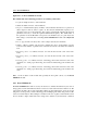
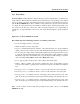
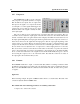
The Comb filter can be used to obtain a vibrato effect on a sound source. In the example of
Figure 11, the output of the LFO modulates the resonance frequencies of the Comb filter. When
the feedback knob is adjusted in the left position and the mod1 knob is opened, the frequency of
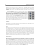
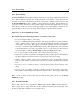
the filtered signal varies with the output from the LFO. When the feedback knob is in the right
position, the filter may start to self-oscillate and be used as a sound source as in the patch of Figure
. In this example, the output of the Noise Mallet is filtered and the resonance frequency of the filter
is controlled with the pitch output from a keyboard. In order to obtain a tempered scale, do not
forget to adjust the mod knob of the filter in the middle position.
Figure 29: A vibrato effect obtained with a Comb filter
Figure 30: Comb and Noise Mallet as a sound source