
User Guide


76 Specifications for modules
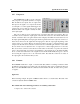
6.13 Bowed Plate
The Bowed Plate module simulates sound produced by bowed rectangular plates of different ma-
terials and sizes. This module first calculates the modal parameters corresponding to plate shaped
objects according to the value of the different parameters requested at construction time and, next,
calls the Bowed Multimode module to simulate sound production by the plate. The module has
one output, the sound produced by the membrane, and three inputs. The first input signal is the
bow velocity in the direction of the motion. The second input signal is a force signal which is
considered to act perpendicularly to the motion of the beam. The third input is a pitch modulation
signal.
Typical Use. See Bowed Multimode module.
The default value of the following parameters is set during construction
• Length: the length, in meters, of the plate.
• Width: the width, in meters, of the plate.
• Frequency: fundamental frequency, in Hertz, of the plate when there is no pitch modulation
signal or when its value is equal to 0. Note that the fundamental frequency is independent of
the size of the plate. The software automatically calculates the physical parameters necessary
to obtain the required fundamental frequency. The default value of this parameter is 261.62
Hz which corresponds to the middle C (C3) of a piano keyboard. This setting is convenient
when controlling a Bowed Plate module with a Keyboard module.
• Decay: proportional to the decay time of the sound produced by the plate.
• Number of Modes: number of modes used to simulate the object. As the number of modes
is increased, the number of partials in the sound increases but also inevitably the calculation
load.
• Excitation point-x: x-coordinate, in meters, of bow from the lower left corner of the plate.
• Excitation point-y: y-coordinate, in meters, of bow from the lower left corner of the plate.
• Listening point-x: x-coordinate, in meters, of listening point from the lower left corner of the
plate. To obtain a proper functioning, the excitation and listening points should be the same.
• Listening point-y: y-coordinate, in meters, of listening point from the lower left corner of the
plate. To obtain a proper functioning, the excitation and listening points should be the same.
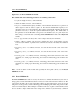
Note: For more details on this module and especially the front panel controls, see the Bowed
Multimode module.