
Operating instructions

OPERATING INSTRUCTIONS
Since most of the parameters used to set up the AM8/4 are adjusted using the AM8/4 Software Control Panel, the
operating instructions include instructions for the use of the software. It’s recommended that you have the software
running, either live or in the demo mode, as you read through this section.
Power Up
When the AM8/4 is powered on, it automatically loads the active setup from Preset 1. Therefore, you should always
store the desired power-up setting for the AM8/4 in Preset 1.
Master/Slave Switch
The Master/Slave switch should be set to the Master position if only one AM8/4 is being used. When multiple AM8/
4s are used in a system, only one is set to Master and the rest are set to Slave. See also the wiring descriptions of
the Audio Expansion In/Out and Expansion In/Out connectors in the Installation section.
Input Preamp Gain
Input preamp gain is set using the dip switches just to the left of each 5 pin input connector. Dip switch settings for
0dB, +30dB, and +50dB input gain are shown on the rear panel of the AM8/4. Generally, the +50dB position is used
for all dynamic microphones and electret microphones where the working distance from the microphone will be
greater than about 18 inches. The +30dB position is useful for electret microphones with working distances less than
18 inches and most wireless microphones. The 0dB setting is for line level sources. Remember to switch phantom
power on for electret microphones and off for dynamic mics or line level sources.
Using the AM8/4 PC Hosted Control Panel
The AM8/4 control panel may be used in one of two ways. When launched from the LecNet Master Pro application,
you can control all the parameters of the AM8/4 in real time. Needless to say, your PC must be connected to the
AM8/4 using the supplied LecNet serial cable in order for this to happen. Alternatively, you can launch the AM8/4
control panel directly and it will automatically come up in the demo mode. The demo mode is useful for doing system
setup (and saving the setups to a disk file) without the need to be connected to an AM8/4.
System setup follows the order of the tabs on the control panel. Start at the left tab and work your way to the right.
Please refer to the AM8/4 Control Panel Software section of this manual for a complete description of each control
panel tab.
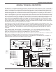
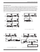
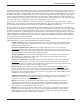
The diagram below represents the signal flow of one input to one output through one matrix crosspoint. Illustrated
are all the gain control points in the signal path.
Input Channel (1 of 16)
Output Channel (1 of 12)
Matrix Crosspoint
(1 of 216)
Mic Preamp
+50dB, +30dB, 0dB
Front Panel
+9dB, to -9dB, Off
Input Gain
+15dB to -63dB, Off
Rear Panel
0dB to -30dB, Off
Mic/Line In
Tone Controls
Front Panel
+9dB to -9dB, Off
Output Gain
+10dB to -68dB, Off
Rear Panel
0dB to -30dB, Off
To Balanced
Output Drive
r
+6dB
+3dB
0dB
-5dB
-10dB
-15dB
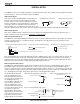
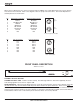
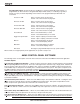
To adjust this parameter: Use this control:
Mic Preamp Gain
Input Gain
Rear Panel (Input) Gain
Output Gain
Rear Panel (Output) Gain
Rear panel dip switches
Input gain tab on AM8/4 control panel software
Programmable inputs on AM8/4 rear panel
Output gain tab on AM8/4 control panel software
Programmable inputs on AM8/4 rear panel
Each input channel has two gain control points, in addition to the rear panel preamp gain switches. The input control
point labeled “Input Trim” is adjusted using the Input Gain tab on the AM8/4 control panel. This control is used to
adjust the sensitivity of each microphone or line level input to the desired gain. The gain adjustment range is +15dB
to -63dB plus off. You may want to increase the mic preamp gain if you find that your input gain settings are routinely
above +10dB.
8