
Operating instructions

8 Channel Automatic Matrix Mixer
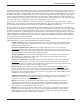
REAR PANEL DESCRIPTION
PWR
IN
(PS60)
16.5 VAC
20VA
M
A
S
T
E
R
S
L
A
V
E
EXPANSION
I
N
O
U
T
LecNet
(RS232)
1 - Prog I/O 1
2 - Prog I/O 2
3 - Prog I/O 3
4 - Prog I/O 4
5 - Prog I/O 5
6 - Prog I/O 6
7 - Prog I/O 7
8 - Prog I/O 8
9 - Prog IN 9
10 - Prog IN 10
11 - Prog IN 11
12 - Prog IN 12
13 - Prog IN 13
14 - +5V
15 - GND
PROGRAMMABLE IN / OUT
AUDIO LINK
I
N
O
U
T
+
––
+ +
––
+
4 3 2 1
+
––
+
2 1
OFF
ON
PHANTOM PWR
12345678
DIR
OUT
+
–
CH8 IN
0dB GAIN
(LINE)
+30dB GAIN
(ELECTRET)
+50dB GAIN
(DYNAMIC)
+
–
CH7 IN
DIR
OUT
DIR
OUT
+
–
CH6 IN
+
–
CH5 IN
DIR
OUT
DIR
OUT
+
–
CH4 IN
+
–
CH3 IN
DIR
OUT
DIR
OUT
+
–
CH2 IN
+
–
CH1 IN
DIR
OUT
CH1 - CH8
OUTPUTS LINE IN
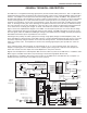
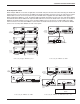
AM8/4 Rear Panel
MIC/LINE INPUTS 1-8 - Accepts balanced or unbalanced signal. Fully balanced differential input, RF filtered.
DIR OUT - Provides a line level signal from each individual channel. The direct output is a post-VCA signal. Any attenua-
tion from the auto mixing process, compressor/leveler system or remote attenuation will be reflected in the direct out signal.
This provides versatility for different mixing applications such as distributed overhead speaker systems. This 100 Ohm
output provides a +20dBu max signal into a high impedance load.
Note: The DIR OUT shares a ground with the OUTPUTS.
--Don’t use the CHANNEL IN grounds for the DIR OUT!--
When connecting to other equipment, the ground connection of the OUTPUTS will also be adequate for
all the direct outputs. A separate ground connection is not needed for each direct out.
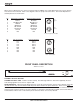
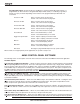
GAIN SELECTION SWITCHES 1-8 - Allows input channel gain to be set. 0dB gain, for line level sources, is set when both
switches of the pair are in the up position. 30dB gain, typically for high output (electret) microphones, is set when the left
switch is in the up position and the right switch is in the down position. 50dB gain, used for low output (dynamic) micro-
phones, is set when both switches are in the down position.
LINE INPUTS 1-2 – Accepts line level balanced or unbalanced axillary inputs. The line inputs do not participate in the
automatic mixing algorithm.
LINE OUTPUTS 1-4 - Provide balanced system outputs. The Line Outputs may also be used in an unbalanced mode by
connecting the “+” terminal of the Line Output to the signal lead of the unbalanced device, and the ground terminal of the
Line Output to the ground of the unbalanced device. Do not connect the “-” terminal of the Line Output.
AUDIO LINK IN/OUT - Provides a means to link the four output buses of multiple AM8/4s. All inputs from all linked AM8/4s
will be available at the outputs of the master AM8/4.
PROGRAMMABLE INPUTS/OUTPUTS - Allows remote control of a number of AM8/4 functions. Pins 1-8 on the 15 pin D-
Sub connector may be programmed to be either programmable inputs or programmable outputs. Pins 9-13 are program-
mable inputs only.
Each of the 13 programmable inputs can utilize either continuous DC voltages (0VDC-5VDC) or contact closures, depend-
ing on the particular function chosen. For continuous voltages, either 10K ohm linear pot or an adjustable DC control
voltage may be used. The volume control action is internally audio scaled in software. This gives an “audio-taper” charac-
teristic to a linear pot. When using a DC control voltage, the control constant is .167V/dB (or 6dB/V) from 0V to 5V. At 0V,
the channel is turned completely off. The control voltage should not exceed 5V.
Programmable outputs allow indication of programmable input states. Each of the 8 programmable inputs is the electronic
equivalent of a contact closure. The logic output will sink up to 100mA at voltages up to 40VDC, however, the total current
draw of all logic outputs should not exceed 50mA if the internal +5V supply is used.
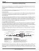
AUDIO EXPANSION IN/OUT - Allows multiple AM8/4s to be linked together when more than 8 inputs are needed. In
multiple AM8/4 setups, one AM8/4 is set to be the Master, and all others are set to be Slaves. The Audio Expansion In of
the Master AM8/4 is connected to the Audio Expansion Out of the first Slave AM8/4, using the supplied LecNet Expansion
cable. The Audio Expansion In of the first Slave AM8/4 is connected to the Audio Expansion Out of the next Slave AM8/4,
and so on.
RS-232 SERIAL PORT - Provides access to and control of some of the operational features of the AM8/4. The port is
compatible with the serial port of a PC, or other controllers with RS-232 type serial ports. For hardware interconnection
and software details, see Appendix 1, “Serial Port Hardware and Software”.
EXPANSION IN/OUT - Allows other LecNet devices to be connected to the AM8/4. Also used when multiple AM8/4s are
connected together to bus the RS-232 serial connection between AM8/4s.
MASTER/SLAVE SWITCH - Sets the AM8/4 for use as a Master device or a Slave device. AM8/4s used singly should be
set for Master mode operation.
PWR IN - Connects to the PS60 power supply to provide power for the AM8/4.
PHANTOM POWER SWITCHES - Allow +15V phantom power to be applied or not on a per-channel basis.
Rio Rancho, NM – USA
7