
Operating instructions
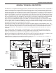
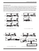
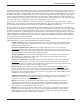

When other LecNet devices are used in conjunction with the AM8/4s, the LecNet Expansion ports of these devices
must also be interconnected. Refer to the diagrams above for proper interconnections. The LecNet Expansion In
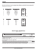
and Out pinouts are shown below.
Pin Expansion In Function Expansion Out Function
1
2
3
4
5
6
7
8
1
2
3
4
5
6
7
8
LecNet
1 Main In Main Out
Expansion
Out
2 Mix Minus Out Mix Minus In
3 NOM In NOM Out
4 NOM Total NOM Total
5 RS-232 RX RS-232 RX
LecNet
6 RS-232 TX RS-232 TX
Expansion
In
7 Ground Ground
8 N/C N/C
LecNet Expansion In/Out
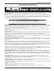
Pin Link In Function Link Out Function
1
2
3
4
5
6
7
8
1
2
3
4
5
6
7
8
Audi
o
1 In 1 Out 1
Link
Out
2 In 2 Out 2
3 In 3 Out 3
4 In 4 Out 4
5 Gnd Gnd
Audi
o
6 N/C N/C
Link
In
7 N/C N/C
8 N/C N/C
Audio Link In/Out
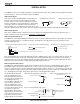
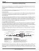
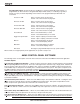
FRONT PANEL DESCRIPTION
AM8/4 Front Panel
LECTROSONICS, INC.
AUTOMATIC MATRIX MIXER
CHANNEL ACTIVITY
1
2
3
4
5
6
7
8
POWER
RESET
DEFAULTS
CHANNEL ACTIVITY SECTION
CHANNEL ACTIVITY LEDS - Indicates channel activity. The LEDs light when the attenuation applied by the auto-
matic mixing algorithm is less than or equal to 6dB.
RESET DEFAULTS – When pressed during power-up, resets the preset memories to their factory defaults. Note that
this will overwrite any user information which may have been stored in the preset memories. There are two reset
modes. If the Reset Defaults button is held in during the first blink of the Power LED after turn-on and then released,
only the preset memories will be set to factory defaults. If the button is held through two blinks of the Power LED, the
LecNet address will be reset to 145 and the preset memories will be set to factory defaults.
6