
Operating instructions

8 Channel Automatic Matrix Mixer
Audio Expansion In/Out
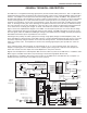
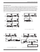
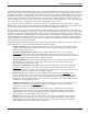
When multiple AM8/4s are used in an application, their Audio Link ports must be interconnected using the Audio Link
In/Out connectors on the rear panel of the AM8/4. The Audio Link In/Out connector is just to the right of the Program-
mable In/Out connector on the rear panel. An 8 pin mini-DIN cable is supplied with each AM8/4 for this purpose.
When installing the AM8/4s in a rack, the Master AM8/4 should be mounted in the top of the rack, with Slave AM8/4s
mounted below the Master AM8/4. The 8 pin mini-DIN cable then connects the Audio Link In connector of the Master
AM8/4 to the Audio Link Out connector of the first Slave AM8/4. If there is more than one Slave AM8/4, the Audio
Link In connector of the first Slave AM8/4 is connected to the Audio Link Out connector of the second Slave AM8/4,
and so on for as many Slave AM8/4s as exist in the system.
M
A
S
T
E
R
S
L
A
V
E
EXPANSION
I
N
O
U
T
AUDIO LINK
I
N
O
U
T
M
A
S
T
E
R
S
L
A
V
E
EXPANSION
I
N
O
U
T
AUDIO LINK
I
N
O
U
T
M
A
S
S
T
E
A
R
L
V
E
EXPANSION
AUDIO LINK
I
N
O
U
T
I
N
O
U
T
Switch in
Switch in
"
MASTER"
"
MASTER"
position
position
Switch in
"SLAVE"
position
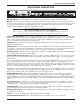
Switch in "EXPAN" position
OUT
IN
EXPANSION
E
X
P
A
N
L
O
C
A
L
TH3 Rear Panel
Switch in
"SLAVE"
position
To additional AM8/4s
Connecting multiple AM8/4s together Connecting the AM8/4 to the TH3
M
A
S
T
E
R
S
L
A
V
E
EXPANSION
I
N
O
U
T
AUDIO LINK
I
N
O
U
T
AM8/4 Rear Panel
AM8 Rear Panel
OUT
IN
EXPANSION
M
A
S
T
E
R
S
L
A
V
E
M
A
S
T
E
R
S
L
A
V
E
EXPANSION
I
N
O
U
T
AUDIO LINK
I
N
O
U
T
AM8/4 Rear Panel
OUT
IN
EXPANSION
E
X
P
A
N
L
O
C
A
L
TH3 Rear Panel
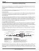
Switch in "EXPAN"
position
AM8/4 Rear Panel
Switch in
"MASTER"
position
M
A
S
T
E
R
S
L
A
V
E
EXPANSION
I
N
O
U
T
AUDIO LINK
I
N
O
U
T
Video
Codec
OUT IN
CODEC
Switch in
"MASTER"
position
Switch in "SLAVE" position
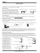
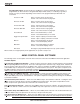
Connecting the AM8/4 to the AM8
Connecting the AM8/4 to the TH3 and a video codec
Rio Rancho, NM – USA
5