
Operating instructions

INSTALLATION
The AM8/4, because it is so highly integrated, is straightforward to install. The following sections explain the installa-
tion and wiring, as well as the software setup of the AM8/4.
AM8/4 Audio Inputs
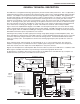
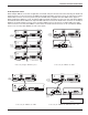
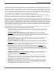
Each of the 8 automatic AM8/4 inputs is balanced, and
Unbalanced Line Level Source
Balanced Line Level Source
provides 15V phantom power (through 2K ohm feed
resistors to the “+” and “-” input connections). Phantom
power is switchable on a per-channel basis. The drawing
to the right shows two examples of line level interface
with the AM8/4; one, an unbalanced line level source and
the other, a balanced line level source. The 2 line inputs are balanced but without switchable Phantom power.
AM8/4 Audio Outputs
Each of the 4 AM8/4 outputs is balanced. To use an output in the unbalanced mode, take the signal from the “+”
output connection and the output ground. Leave the “-” output floating.
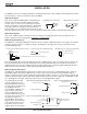
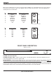
AM8/4 Programmable Inputs
The AM8/4 has 13 programmable inputs which can control a variety of AM8/4 parameters. Each input can respond
to either a contact closure or a continuous voltage. The diagram to the right shows common connections to the
programmable input pins.
Pot Connection for Analog Control of Gain
Contact Closure as Programmable Input DC Voltage Source as Programmable Input
Input +
Input -
Gnd
Input +
Input -
Gnd
1k Ohm
To Programmable Input Pin
10K Linear Pot
To Programmable Input Pin
0VDC (Off) to +5VDC (On)
Gnd
CCW
CW
Gnd
+5V
To Programmable Input Pin - 1k series resistor recommended
Gnd
Each programmable input is internally pulled up through a 100K resistor to +5V, so no external pull up resistors are
necessary. When using a continuous voltage with one of the programmable inputs, the Function of the program-
mable input must be set to either Analog In Control or Analog Out Control. See the Programmable Input tab in the
AM8/4 Control Panel software for setting all programmable input parameters.
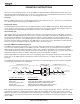
AM8/4 Programmable Outputs
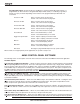
The AM8/4 has 8 programmable outputs which can indicate the current state of a programmable input. Each pro-
grammable output is the electrical equivalent of a contact closure to ground. When a programmable output is
“active”, it conducts current to ground. When the programmable output is “inactive”, no current flows to ground. The
maximum usable voltage for the programmable outputs is 40V, and they will safely conduct up to 100mADC continu-
ous. The diagram on the right shows some typical uses for the programmable outputs.
It is permissible to run LEDs
LED is on when the programmable output is active
LED is off when programmable output is active
+5VDC (from Pin 14)
380
380
from the +5VDC pins on the
+5VDC (from Pin 14)
programmable input connector,
Ohms
Ohm
s
as long as the total LED current
Programmable Output Pin
for all LEDS on does not
exceed 100mA. Similarly, 5V
Programmable Output Pin
relay coils may also be run
from the +5VDC pins on the
GND (from Pin 15)
programmable input connector,
as long as the total coil current
Relay is on when programmable output is active
for all relays on does not
exceed 50mA. Note that the
External DC Voltage
diagram shows an external DC
Source (<40VDC)
source powering the relay coil.
Programmable Output Pin
This will be necessary if coil
GND (from Pin 15)
voltages above 5V are needed.
Relay Coil
Coil current < 100mA
1N4001
or equiv.
4