
Operating instructions

8 Channel Automatic Matrix Mixer
GENERAL TECHNICAL DESCRIPTION
The AM8/4 uses a straightforward analog signal path to provide excellent audio performance. This is coupled with a
sophisticated microcontroller to implement the automatic mixing, matrix control, and programmable input and output
functions. The Adaptive Level Proportional automatic mixing algorithm is used by the AM8/4. This algorithm uses
the signal level pattern at the microphones to derive a pattern of channel gains. For instance, if only one microphone
channel is being spoken into, its level is dominant and that channel gets most of the system gain, while all other
channels are turned down. If more than one microphone is active, they share system gain according to their relative
levels. A “skewing” function gives some advantage to microphones which are active over time, to minimize interrup-
tions from transient noise at other microphones. Since the gain of each channel is apportioned continuously based
on its relative level, no abrupt gain changes are made. This makes the automatic action virtually inaudible.
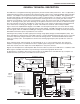
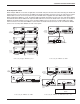
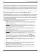
Figure 1 shows the simplified block diagram of the AM8/4. The microphone preamp is a low-noise discrete design,
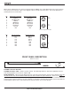
which is extensively RF protected. The preamp has three gain settings. The 0dB setting allows an input to accept
line level signals, while the +30dB and +50dB gain settings accommodate both low and high sensitivity microphones.
Switchable 15V Phantom power is provided for each channel.
Following the mic preamp, the audio signal passes through a high quality Voltage Controlled Amplifier (VCA). This
VCA, controlled by a signal from the system D/A converter, is used to implement both static gain control (i.e. mic trim
and remote input level) and gain reduction for the automatic mixing function. A Channel On LED indicates which
inputs are currently active. A sweepable low-cut filter and a shelving high frequency filter provide tone control for
each input.
The 8 automatic inputs and 2 line inputs are routed through an 11 in / 4 out crosspoint matrix. The matrix has
multiple crosspoint gains to accommodate the most complex signal routing needs. Aside from the 10 inputs, the
matrix also includes one other inputs: the LecNet Expansion In rear panel connector.
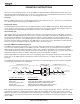
Signals from the Expansion In and Expansion Out connectors allow easy interface to AM8 mixers. In addition, a Mix
Minus signal is available which allows easy interfacing to teleconferencing hybrids like the TH3.
An RS-232 port is available to allow many of the functions of the AM8/4 to be controlled either by a computer or a
dedicated control system (such as the AMX or Crestron systems).
EXPANSION
IN
EXPANSION
OUT
LECNET
PORT
(RS-232)
AM8/4
Block
AUDIO
Diagram
LINK IN
AUDIO
LINK OUT
+
-
MIC
PREAMP
TO
A/D CONVERTER
AUTO INPUT (1 OF 8)
+15V
SERIAL
BUS
MAIN IN
MIX MINUS OUT
AUTO MIX LOG IN
AUTO MIX
LOG OUT
MIX MINUS IN
MAIN OUT
TX
RX
PHANTOM
POWER
VARIABLE LOW CUT
HIGH CUT/BOOST
LINE INPUT (1 OF 2)
INPUT
LEVEL
SPEECH
FILTER
LOG
CONVERTER
AUDIO
VCA
FROM D/A
CONVERTER
VARIABLE LOW CUT
HIGH CUT/BOOST
PREAMP GAIN
0dB (LINE)
+30dB (MIC)
+50dB (MIC)
FROM INPUT
FROM INPUT
FROM INPUT
FROM INPUT
FROM INPUT
FROM INPUT
FROM INPUT
FROM LINE INPUT
FROM LINE INPUT
2
3
4
5
6
7
8
1
2
PROCESSOR
CONTROLLED
SWITCH
ARRAY
uC
68HC12
BALANCED
LINE OUTPUT 1
BALANCED
LINE OUTPUT 2
BALANCED
LINE OUTPUT 3
BALANCED
LINE OUTPUT 4
15dB
15dB
15dB
15dB
PROCESSOR
CONTROLLED
VARIABLE
RESISTOR
PROCESSOR
CONTROLLED
ATTENUATORS
1
2
3
4
5
6
7
8
9
10
11
12
13
PROGRAMMABLE I/O
PROGRAMMABLE I/O
PROGRAMMABLE I/O
PROGRAMMABLE I/O
PROGRAMMABLE I/O
PROGRAMMABLE I/O
PROGRAMMABLE I/O
PROGRAMMABLE I/O
PROGRAMMABLE INPUT
PROGRAMMABLE INPUT
PROGRAMMABLE INPUT
DIR OUT
PROGRAMMABLE INPUT
PROGRAMMABLE INPUT
PROCESSOR
CONTROLLED
VARIABLE
RESISTOR
PROCESSOR
CONTROLLED
VARIABLE
RESISTOR
MIC IN +
MIC IN -
MIC GND
CHANNEL ON
1 OF 8
LINE IN +
LINE IN -
1 OF 2
MIX BUS 1
MIX BUS 2
MIX BUS 3
MIX BUS 4
Rio Rancho, NM – USA
3