
Operating instructions
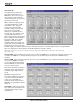
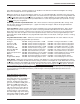
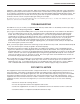

SERIAL CABLE WIRING DIAGRAMS
LecNet Device to PC
S
R
3.5MM
9 or 25 Pin Female
T
Stereo Plug D-Subminiature
LecNet Device Transmit
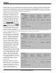
Wiring Diagram, 9 Pin D-Sub
LecNet Port
N/C
CD
Tip
RX
Ring
LecNet Device Receive
TX
Sleeve
Gnd
DTR
Gnd
DSR
RTS
CTS
N/C
RI
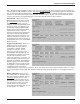
Wiring Diagram, 25 Pin D-Sub
1
2
3
Host
4
Serial
5
Port
6
(PC)
7
8
9
Tip
LecNet Device Transmit
RX
3
Ring
LecNet Device Receive
TX
2
Sleeve
Gnd
Sig Gnd
7
Host
Chassis Gnd
1
Serial
LecNet Port
RTS
CTS
4
Port
5
(PC)
DSR
6
DTR
20
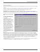
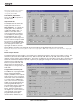
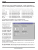
LecNet Device to AMX or Crestron
S
R
3.5MM
9 Pin Female
T
Stereo Plug D-Subminiature
N/C
1
Tip
LecNet Device Transmit
RXD
2
Ring
LecNet Device Receive
TXD
3
AMX
Sleeve
Gnd
N/C
4
or
Gnd
5
LecNet Port
Crestron
N/C
6
Port
N/C
7
N/C
8
N/C
9
The serial port on the AM8/4 is a minimal RS-232
implementation. The figure shows the wiring diagram
to
accommodate interconnection with either a 9 or a 25
pin serial port on a PC or other serial device.
AMX Programming Notes
If you are using an AMX system to control your
LecNet equipment, you’ll want to purchase the
Lectrosonics PT3 Protocol Translator. The PT3
connects between the AMX bus and any LecNet
equipment. With the PT3, the LecNet equipment
looks just like native AMX equipment. The PT3 is the
fastest and most productive way to control LecNet
devices with an AMX system.
20