
Operating instructions

Programmable Output - Sets one of programmable I/Os 1-8 to the programmable output mode. Programmable
outputs indicate the state of functions controlled by programmable inputs. For example, if programmable I/O 1 is set
to Mute output 1, setting programmable I/O 2 to Programmable Output and connecting its Applies To function to Prog
Input State 1 means that programmable output 2 will be active when output 1 is unmuted and inactive when output 1
is muted.
A programmable I/O whose function is set to Programmable Output will be active (i.e. conducting to ground) or
inactive (i.e. open) as follows depending on the function of the programmable input with which it is associated:
Analog In: Active - Analog In attenuation < 15dB Inactive - Analog In attenuation >= 15dB
Increase In 1dB: Active - Contact closure on prog input Inactive - No contact closure on prog input
Decrease In 1dB: Active - Contact closure on prog input Inactive - No contact closure on prog input
Analog Out: Active - Analog Out attenuation < 15dB Inactive - Analog Out attenuation >= 15dB
Increase Out 1dB: Active - Contact closure on prog input Inactive - No contact closure on prog input
Decrease Out 1dB: Active - Contact closure on prog input Inactive - No contact closure on prog input
Preset Recall: Active - Associated memory is active Inactive - Associated memory is not active
Toggle Crosspoint Gain Active - Selected input is sent to outputs Inactive - Selected input is not sent to outputs
Mute In: Active - Associated input(s) not muted Inactive - Associated input(s) muted
Mute Out: Active - Associated output(s) not muted Inactive - Associated output(s) muted
Programmable Output: Active - Associated prog in function active Inactive - Associated prog in function inactive
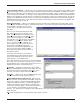
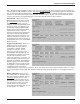
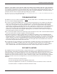
The screen below shows Programmable In 1 set to the Programmable Out function.
Not Used - Unprograms a programmable i/o such that there will be no action associated with it.
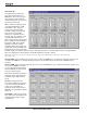
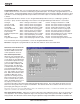
Remote I/O Level Controls Tab
The Remote I/O Level Controls
tab allows AM8/4 remote level
control parameters to be set.
Rear Panel Input Controls -
Allows the rear panel input gain
control adjustment range to be set
to safe levels for user adjustment.
The maximum adjustment range
of the rear panel input control
goes from 0dB to -30dB (in 1dB
steps) plus Off. The Min Gain
scroll bar allows the gain adjust-
ment range below 0dB to be
limited as needed for the applica-
tion. “Off” signifies no lower gain
limit. 0dB is the maximum value
available for Min Gain, and is
equivalent to making rear panel
input control inactive. The Gain
Preset scroll bar allows a preset
gain to be applied at power on to
any input(s) controlled by the
Increment Input 1dB or Decrement Input 1dB programmable input function. The control panel will always force the
Gain Preset to be greater than or equal to the Min Gain. The 10 boxes below the scroll bars show the current rear
panel input gain setting for each input.
Short Cuts: A left mouse click on the Min Gain box will set the minimum gain to Off (i.e. no limit on the minimum gain), while a
right mouse click will set the minimum gain to 0dB.
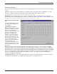
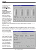
Rear Panel Output Controls - Allows the rear panel output gain control adjustment range to be set to safe levels for
user adjustment. The maximum adjustment range of the rear panel output control goes from 0dB to -30dB (in 1dB
steps) plus Off. The Min Gain scroll bar allows the gain adjustment range below 0dB to be limited as needed for the
18