
Installation guide

5522
© 2005 Directed Electronics—all rights reserved
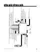
ttaabbllee ooff zzoonneess
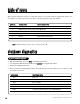
When using the Diagnostic functions, use the Table of Zones to see which input has triggered the system. It is
also helpful in deciding which input to use when connecting optional sensors and switches.
NNOOTTEE
: The Warn Away® response does not report on the LED.
sshhuuttddoowwnn ddiiaaggnnoossttiiccss
1. With the ignition OFF, press and
HHOOLLDD
the Valet/Program button.
2. Turn the ignition ON and then back OFF while
HHOOLLDDIINNGG
the Valet/Program button.
3. Release the Valet/Program button.
4. Press and release the Valet/Program button. The LED will report the last shutdown for one minute or until
the ignition is turned on.
LLEEDD FFLLAASSHHEESS SSHHUUTTDDOOWWNN MMOODDEE
One Timed out
Two Over-rev shutdown
Three Low or no RPM
Four Transmitter shutdown (or optional push-button)
Six (-) Shutdown (H3/4 GRAY) or (+) Shutdown (H3/3 BROWN)
Seven (-) Neutral safety shutdown (H3/1 BLACK/WHITE)
Eight Wait-to-start timed out
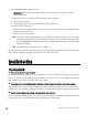
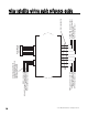
ttoo ppeerrffoorrmm sshhuuttddoowwnn ddiiaaggnnoossttiiccss
ZZOONNEE NNOO.. TTRRIIGGGGEERR TTYYPPEE IINNPPUUTT DDEESSCCRRIIPPTTIIOONN
1 Trunk Input BLUE (H1/7)
2 Multiplexed Shock Sensor Input Mux BLUE wire.
3 Door Trigger GREEN (H1/8) and VIOLET (H1/6).
4 Multiplexed Shock Sensor Input Mux GREEN wire
5 Ignition Yellow ribbon harness wire
6 Hood Brake Trigger GRAY on the 6-pin shutdown harness.