
Specifications


Table Of Contents
- Color StyleWriter 6500
- Basics
- Specifications
- Troubleshooting
- Take Apart
- Paper Tray
- Top Cover
- Access Door
- Side Access Door
- Keypad Bezel
- Lightpipe Assembly
- Base
- Logic Board EMI Shield
- Power Supply EMI Shield
- Logic Board
- Power Supply Board
- Flex Clamp
- Ribbon Cable
- Access Door Actuator
- Ground Plane
- Encoder Strip
- Encoder Stiffener
- Carriage Belt
- Turnaround Assembly
- Idler Assembly
- Carriage Motor
- Purge Unit
- Absorber Assembly
- Purge Unit Motor
- Paper Motor
- Mechanical Assembly
- Additional Procedures
- Exploded View
Additional Procedures X-Y Calibration - 49
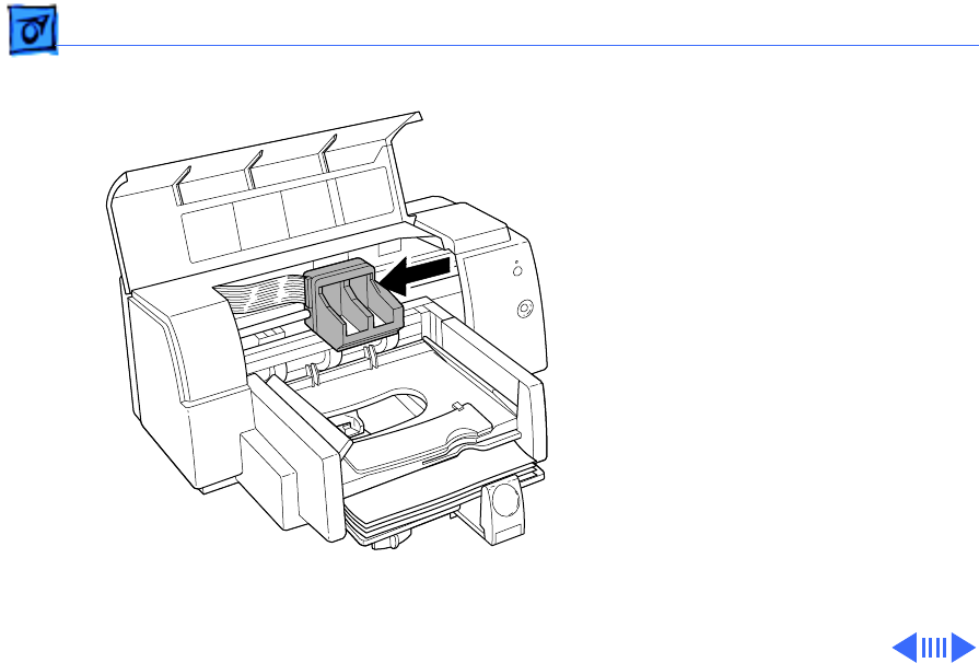
4 Open the front cover and
locate the X and Y values
on the right side of the
printer’s carriage.
5 Enter the X and Y values
using the utility’s pop-
up menus.
6 Close the front cover
and press Send File. Wait
for the utility to write
the X and Y values into
printer memory and
print the Extended
Diagnostic Test page,
shown on the next page.
Figure: X-Y Values at Right Side of Carriage