
Specifications


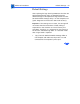


Table Of Contents
- Color StyleWriter 6500
- Basics
- Specifications
- Troubleshooting
- Take Apart
- Paper Tray
- Top Cover
- Access Door
- Side Access Door
- Keypad Bezel
- Lightpipe Assembly
- Base
- Logic Board EMI Shield
- Power Supply EMI Shield
- Logic Board
- Power Supply Board
- Flex Clamp
- Ribbon Cable
- Access Door Actuator
- Ground Plane
- Encoder Strip
- Encoder Stiffener
- Carriage Belt
- Turnaround Assembly
- Idler Assembly
- Carriage Motor
- Purge Unit
- Absorber Assembly
- Purge Unit Motor
- Paper Motor
- Mechanical Assembly
- Additional Procedures
- Exploded View
Additional Procedures Default Settings - 46
Verifying Default Settings
Verify the logic board was reset to the “customer mode”.
Look at the NVM table at the bottom of the Extended
Diagnostic Page (shown on the preceding page). The first two
NVM addresses (upper left of the table) should display a
“00 00”. Also, on the first row, the last thirteen pairs of
numbers should read 43 6f 6c 6f 72 53 74 79 6c 65
57 72 69. If they read “ff”, then the incorrect version of
the Default Settings program is being used. The correct
version can be identified by the modification date on the file.
The correct file has a date of May 4, 1998.
Note: After replacing the logic board, carriage, or
mechanical assembly you must also use the Color SW 6500
X-Y Calibration utility to set factory default carriage values
in printer memory. Refer to the “X-Y Calibration”
procedure that follows.