
Specifications

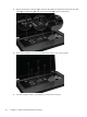


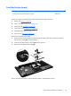
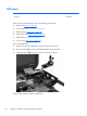
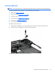
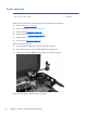
Table Of Contents
- Product description
- External component identification
- Illustrated parts catalog
- Removal and replacement procedures
- Specifications
- Setup Utility (BIOS)
- Backup and recovery
- Power cord set requirements
- Recycling
- Index
5.
Remove the three Phillips 3.0 x 2.0 screws in the battery bay, two Phillips 3.0 x 2.0 screws in the
optical drive bay, and ten Phillips 6.0 x 2.5 on the base enclosure.
NOTE: The four screws along the front edge also serve to secure the speakers inside the base
enclosure.
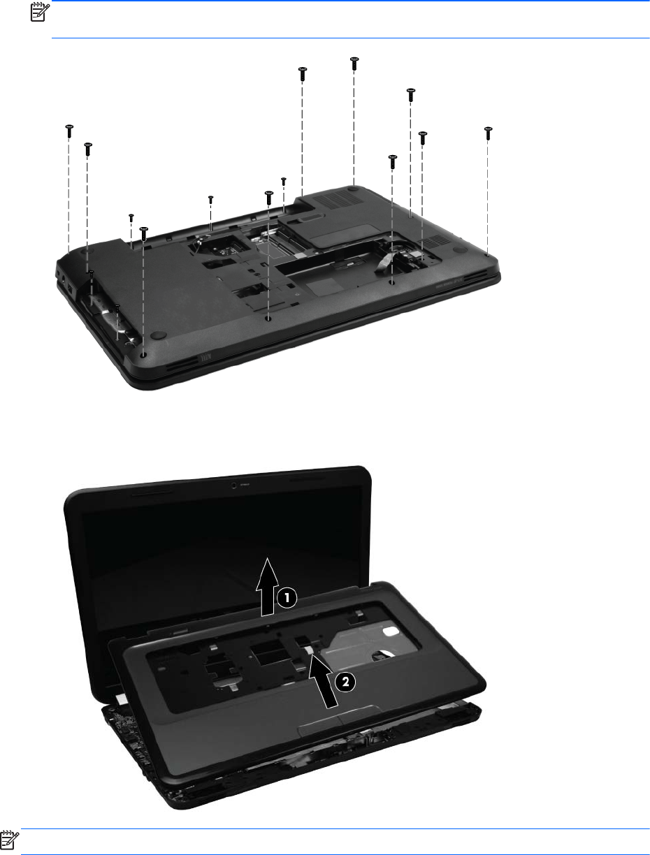
6. Lift the rear edge of the top cover (1) until the top cover disengages from the base enclosure.
Remove the top cover (2).
NOTE: The TouchPad is glued to the top cover and is included with the top cover spare part.
Component replacement procedures
55