Service Source MacBook Pro 17-inch (original, Core 2 Duo, 2.4 GHz, Late 2007 CTO, Early 2008, and Late 2008) Updated 14 October 2008 © 2008 Apple Inc. All rights reserved.
Apple Inc. © 2008 Apple Inc. All rights reserved. Under the copyright laws, this document may not be copied, in whole or in part, without the written consent of Apple. Every effort has been made to ensure that the information in this document is accurate. Apple is not responsible for printing or clerical errors. Apple 1 Infinite Loop Cupertino, CA 95014-2084 USA + 1 408 996 1010 www.apple.com Apple, the Apple logo, Mac, and Macintosh are trademarks of Apple Inc., registered in the U.S.
MacBook Pro 17-inch Contents Basics General Information 7 Product View Overview 7 7 Take Apart Foot 15 Battery 18 Memory 20 Replacement Procedure Top Case 25 Keyboard 35 Replacement Procedure Replacement Procedure 23 30 50 AirPort Extreme Card 59 Hard Drive/SSD 64 Bluetooth Card and Antenna Infrared Board 75 Replacement Procedure 69 77 Optical Drive 79 Handling Slot-Load Optical Drives 84 Replacement Procedure 87 Removing a Stuck Disc from an Optical Drive 88 Backup Battery 90 Ambient
ExpressCard Cage Fans 110 111 Logic Board 118 Replacement Procedure 128 Battery Cable Assembly 135 Thermal Sensors 137 Heatsink 141 Bottom Case 143 Display Assembly 145 Replacement Procedure 148 Adjustments Latch Adjustment 152 Troubleshooting General Information 156 Wire and Flex Cables 156 Microphone and Camera wires 157 Hardware Diagnostics 157 Troubleshooting Aids and Tips 159 MacBook Pro Firmware Updates 161 Software Troubleshooting Tips and Tools 162 Troubleshooting Steps 164 Hardware Symp
Microphone 184 Modem (External) 184 Optical Drive 186 Ports 187 MagSafe Power Adapter 188 Sound 189 Trackpad 190 Video 191 Miscellaneous Symptoms 192 Architecture 195 Views MacBook Pro (17-inch original) Exploded View 198 MacBook Pro (17-inch Core 2 Duo) Exploded View 199 MacBook Pro (17-inch 2.
Service Source Basics MacBook Pro 17-inch (original, Core 2 Duo, 2.4 GHz, Late 2007 CTO, Early 2008, and Late 2008) © 2008 Apple Inc. All rights reserved.
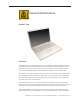
General Information Product View Overview The MacBook Pro 17-inch family (original, Core 2 Duo, 2.4/2.6GHz, and 2008 models) represents four generations of Apple’s Intel-based professional 17-inch portables. The original MacBook Pro 17-inch had an Intel Core Duo chip, the 17-inch (Core 2 Duo and 2.4GHz) had successive Intel Core 2 Duo chips, and the MacBook Pro (Early and Late 2008) models contains the new Intel Penryn chip. The Intel Penryn architecture supports faster clock speeds of 2.
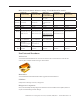
Main service and feature differences among 17-inch MacBook Pro models: Intro Date MacBook Pro (17-inch Late 2008) MacBook Pro (17-inch Early 2008) MacBook Pro (17-inch 2.4GHz + Late 2007 2.6GHz CTO*) MacBook Pro (17-inch Core 2 Duo) MacBook Pro (original 17-inch) October 14, 2008 February 26, 2008 June 5, 2007 / Nov 1, 2007 October 24, 2006 April 24, 2006 2.5GHz Penryn and 2.6GHz (CTO) 2.4GHz Core 2 Duo + *2.6GHz CTO (Late 2007) 2.33GHz Core 2 Duo 2.16GHz Core Duo Micro- 2.
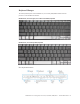
Keyboard Changes The new keyboard layout on the MacBook Pro (17-inch Early 2008) differentiates it from all previous 17-inch MacBook Pro models. MacBook Pro (17-inch original, Core 2 Duo and 2.4GHz) keyboard MacBook Pro (17-inch Early 2008) keyboard New keyboard features MacBook Pro 17-inch (original, Core 2 Duo, 2.4/2.
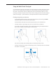
Using the Multi-Touch Trackpad Use the trackpad to move the pointer and to scroll, tap, double-tap, and drag. How far the pointer moves on screen is affected by how quickly you move your finger across the trackpad. To move the pointer a short distance, move your finger slowly across the trackpad; the faster you move your finger, the farther the pointer moves. To fine-tune the tracking speed and set other trackpad options, choose Apple > System Preferences, click Keyboard & Mouse, and then click Trackpad.
New trackpad gestures: pinching, rotating and swiping The following trackpad gestures work in certain applications, such as Preview or iPhoto. For more information, choose Help > Mac Help and search for “trackpad.” • Two-finger pinching lets you zoom in or out on PDFs, images, photos, and more. • Two-finger rotating lets you rotate photos, pages, and more. • Three-finger swiping lets you rapidly page through documents, move to the previous or next photo, and more.
Serial Number and Ethernet ID The Serial Number and Ethernet ID are located in the battery bay.
Display Takeapart The MacBook Pro (17-inch Early 2008) continues the whole display clamshell solution as the replacement part for any display failures or components contained within the clamshell. Electrostatic Discharge (ESD) Use a properly grounded ESD wrist strap and mat when working on the inside of the computer.
Service Source Take Apart MacBook Pro 17-inch (original, Core 2 Duo, 2.4 GHz, Late 2007 CTO, Early 2008, and Late 2008) © 2008 Apple Inc. All rights reserved.
Foot Tools This procedure requires the following tools: • Foot kit • Tweezers or needlenose pliers • Soft cloth Preliminary Step Before you begin, check the foot location that needs replacement and verify that the case plug is attached. Also verify that the case plug, and the case foot in the kit, match the pictures below. Plug Area on Bottom Case Matching Foot Action Missing case plug Not available for replacement Replace the bottom case, or send to Apple Repair Center.
Procedure Warning: The glue used in this procedure can bond instantly to skin. Do not touch the glue. In the event of contact, review the safety instructions at the end of this document. For additional information, refer to the glue manufacturer: Elmer’s Products, Inc. Columbus, OH. 43215-3799 www.krazyglue.com 1. Place the computer upside down on a clean, lint-free cloth or other nonabrasive surface. 2. Select a foot from the kit.
4. Warning: GLUE IS AN EYE AND SKIN IRRITANT. BONDS SKIN INSTANTLY. Do not touch the glue at any time. Before opening the glue, review the safety instructions below. Important: The glue tube included in the kit is sealed until first use. Do not break the seal until you are ready to use the glue. To break the seal, hold the tube upright and away from you. Place the hollow nozzle cap on the tube and tighten it all the way down. The tube is then ready to dispense the glue through the nozzle cap. 5.
Battery Tools This procedure requires the following tools: • Clean non-marring work surface Preliminary Steps Warning: Always shut down the computer before opening it to avoid damaging its internal components or causing injury. After you shut down the computer, the internal components can be very hot. Let the computer cool down before continuing. Part Location MacBook Pro 17-inch (original, Core 2 Duo, 2.4/2.
Procedure Warning: If the computer has been recently operating, allow it to cool down before performing this procedure. 1. Shut down the computer. 2. Disconnect the power cord and any other cables connected to the computer. 3. Place the computer upside down. 4. Slide both battery latches away from the battery and lift the battery out of the battery bay. MacBook Pro 17-inch (original, Core 2 Duo, 2.4/2.
Memory Tools This procedure requires the following tools: • #0 Phillips screwdriver (magnetized) • Clean non-marring work surface • ESD wrist strap and mat Preliminary Steps Before you begin, remove the following: • Battery Part Location MacBook Pro 17-inch (original, Core 2 Duo, 2.4/2.
Procedure Warning: If the computer has been recently operating, allow it to cool down before performing this procedure. 1. Place the computer upside down. 2. Remove four screws from the memory door. 3. Remove the door, as shown. Notes: • If only one memory card is installed, the factory installs it in the bottom memory slot. • Memory must be removed from the top slot before removing from the bottom slot. MacBook Pro 17-inch (original, Core 2 Duo, 2.4/2.
4. To remove memory cards, carefully spread the two locking tabs for the slot (top or bottom) away from the card on both sides and allow the card to pop up slightly. 5. Pull the card straight back and out of the memory slot. Handle the memory card by the edges only, taking care not to touch the gold contacts. MacBook Pro 17-inch (original, Core 2 Duo, 2.4/2.
Replacement Procedure Notes: • DDR memory cards do not fit in this slot, only DDR2 (different notch location). • If installing two cards, install into the bottom slot first. • Align the notch in the memory card with the tooth in the slot before inserting. 1. To install memory cards, insert them at a 30-degree angle. Note: Insert the bottom card behind the locking tabs of the top slot. 2. Firmly push the card straight into the slot until it is fully and securely seated along its length.
4. Verify that the card is fully seated by pushing firmly with your thumbs. 5. Check that the cards are secured by the brackets on both sides. 6. Install the memory door. 7. Replace the battery. 8. Use Apple System Profiler to verify that the memory is recognized. (Choose the menu bar Apple logo () > About This Mac, click More Info..., select the System Profile tab, open the Memory Overview.
Top Case Tools This procedure requires the following tools: • #0 Phillips screwdriver (magnetized) • Torx T6 screwdriver (magnetized) • Black stick (nylon probe 922-5065) or other non-conductive nylon or plastic flat-blade tool • Multi-compartment screw tray (such as a plastic ice cube tray) Preliminary Steps Before you begin, remove the following: • Battery • Memory Part Location MacBook Pro 17-inch (original, Core 2 Duo, 2.4/2.
Procedure Notes: • This procedure removes the top case and keyboard assembly. The keyboard is removable only after removing the top case. 1. Place the computer upside down. 2. Remove the nine screws shown. 3. Remove the four screws from each side. 4. Remove the two screws from the back edge. . MacBook Pro 17-inch (original, Core 2 Duo, 2.4/2.
5. Face the computer toward you with the display open slightly past 90-degrees. Using your fingernails or the tips of your fingers, grasp just beneath the back edge of the top case behind the keyboard or in the upper right and left corners. Lift upward a few inches, then work your hands around the top case toward the front, slowly lifting and encouraging the clips and screw tabs to release. A snapping noise when the clips release is normal. MacBook Pro 17-inch (original, Core 2 Duo, 2.4/2.
Note: Take care to preserve the cosmetic integrity of the plastic beading around the edges of the top case. If using a black stick for leverage to get the clips to release, don’t rotate the stick too vigorously along the edges to avoid denting the soft plastic. 6. Along the front, start at the left and slowly encourage the snaps and screw tabs (shown in graphic below) to release as you move right. A snapping noise as the snaps release is normal.
Important: To avoid bending screw tabs along the back edge of the top case, lift the top case slightly so that it does NOT touch the bottom case, then rotate the front of the case up and back until you can disconnect the keyboard flex cable from the logic board. MacBook Pro 17-inch (original, Core 2 Duo, 2.4/2.
Replacement Procedure Note: If replacing the top case, remove the Keyboard and transfer to the replacement top case. 1. Visually check to verify that all cables are connected and routed correctly with nothing raised up or incorrectly over a component. 2. Check perimeter wiring and cables around clutches to verify that they will not be caught or pinched by the top case during replacement. 3. On the computer, verify that all cables are secure and lay flat. 4.
5. Check that the perimeter screw tabs and ribs are not bent. Note: The metal can quickly fatigue and break off. Be extremely careful to gently straighten tabs, if needed. 6. Verify that the screw tabs in back are straight and guide them inside the bottom case. Work your way around guiding the screw tabs into the bottom case along both sides. MacBook Pro 17-inch (original, Core 2 Duo, 2.4/2.
7. If the back screw tabs are bent out, straighten by pressing the edge of the case on a hard flat surface and rolling to vertical. 8. Any screw tabs that are not straight will not fit or accept screws correctly. MacBook Pro 17-inch (original, Core 2 Duo, 2.4/2.
9. Use your finger and a black stick to carefully straighten bent screw tabs. 10. Connect the flex cable from the top case to the logic board. 11. Lift the top case off the bottom case slightly and rotate it down (verify that the keyboard cable stays connected and is folding properly) and align the corners. 12. Carefully pull or push tabs slightly, if needed. Note: Guarded, controlled pushing with your thumb may be helpful to finesse the tabs into place. 13.
16. Install the bottom screws. 17. Install the two screws along the back. . 18. Install the memory door and replace the battery. 19. Testing the computer should include: • Powering on, checking the keyboard and trackpad function. • Operate the computer in a darkened room to check for keyboard backlight function. MacBook Pro 17-inch (original, Core 2 Duo, 2.4/2.
Keyboard Tools This procedure requires the following tools: • #0 Phillips screwdriver (magnetized) • Razor knife • Needlenose pliers • Black stick (nylon probe 922-5065) or other non-conductive nylon or plastic flat-blade tool • Kapton tape (922-1731) (0.5-inch x 12-yard roll) Preliminary Steps Before you begin, remove the following: • Battery • Top Case Part Location MacBook Pro 17-inch (original, Core 2 Duo, 2.4/2.
Procedure Important Notes: • All 17-inch MacBook Pro keyboards are not interchangeable with previous PowerBook models nor any 15-inch MacBook Pros. Verify that the correct replacement keyboard is ordered, and/or top case if replacing. • In addition, keyboards for all models of the 17-inch MacBook Pro are not interchangeable, ie, side tabs were removed on the MacBook Pro 17-inch (2.
3. Peel off any tape to gain access to the connector. 4. Locate the protective cover over flex cable connectors. This will not be removed, but released only half way around to access the large flex cable connector. MacBook Pro 17-inch (original, Core 2 Duo, 2.4/2.
5. Use a razor knife to carefully lift up at the edge just enough to slide in the flat side of a black stick. 6. To release the adhesive, slide the black stick around the front half perimeter only, as shown. 7. When disconnecting or installing the large flex cable, carefully lift the front of the cover. Important: Keep the cover and its adhesive clean. MacBook Pro 17-inch (original, Core 2 Duo, 2.4/2.
8. Carefully disconnect the two connectors, shown below, and slide out their flex cables. The direction that the connector lock bars release is shown in the illustration below. Important: The connectors are delicate. If damaged, the top case must be replaced. Note: The clear cover is shown removed here, for clarity only. 9. Release the adhesive under the large flex cable. MacBook Pro 17-inch (original, Core 2 Duo, 2.4/2.
10. Locate the insulator film covering the back of the keyboard well. The film will NOT be removed, but will be peeled back to first access four bend-tabs in the MacBook Pro (17-inch and 17-inch Core 2 Duo) and six bend-tabs in the MacBook Pro (17-inch 2.4GHz and Early 2008) along the bottom edge, and then to access some keyboard screws. 11. Use a razor knife to carefully lift up at the edge just enough to slide in a black stick. Important: Do NOT cut the film with the knife.
12. Use the black stick to defeat the adhesive at the edge so that the film can be peeled back to access the bend tabs. Important: When peeling, use care at perforations, notches and narrow parts to avoid ripping the film. 13. Peel back the film to access the bend-tabs. Note: Both films are peeled back here to show tab location, but you should work on one side at a time. Note: There are four bend-tabs in the MacBook Pro (17-inch and 17-inch Core Duo) and six bend-tabs in the MacBook Pro (17-inch 2.
14. Use needlenose pliers to gently and carefully straighten the bend-tabs located along the bottom edge, as shown. These tabs lock down and stiffen the top edge of the keyboard. Important: The bend-tabs are delicate. Bend with care to avoid damage. Avoid over-bending. (a) MacBook Pro (17-inch) and MacBook Pro (17-inch Core 2 Duo) have four bend-tabs. (b) MacBook Pro (17-inch 2.4GHz) and (17-inch Early 2008) have six bend-tabs. MacBook Pro 17-inch (original, Core 2 Duo, 2.4/2.
15. Remove the Phillips #00 keyboard screws. Locations shown below. Be sure to sandwich keyboard to top case when removing the final screws. (a) MacBook Pro (17-inch) and MacBook Pro (17-inch Core 2 Duo) each have ten screws. (b) MacBook Pro (17-inch 2.4GHz) and (17-inch Early 2008) have twelve screws (one extra screw on each side). Note: Photo below is for screw location identification only. Proceed with the procedure with the Mylar film still in place as above.
16. Carefully peel back the film as needed to access the screws. 17. To prevent the keyboard from falling out, support it with your hand, and raise the top case up vertically. Note: Since the MacBook Pro 17-inch (2.4GHz & Early 2008) keyboards have no side tabs like previous models, the keyboard will more easily fall out of the keyboard well. MacBook Pro 17-inch (original, Core 2 Duo, 2.4/2.
18. Note the six insert-tabs along the bottom edge of the keyboard that tuck into the lower edge of the keyboard well of the MacBook Pro (17-inch 2.4GHz) and (17-inch Early 2008). Note: The MacBook Pro (17-inch) and MacBook Pro (17-inch Core 2 Duo) have 2 more sets of tabs on the sides which hold the keyboard in place, making keyboard extraction more complex. For instructions on keyboard removal for these models, skip forward to step 21.) MacBook Pro 17-inch (original, Core 2 Duo, 2.4/2.
19. The MacBook Pro 17-inch (2.4GHz and Early 2008) keyboard may simply fall free of the top case if you lean it toward you top first. Note: For instructions on keyboard removal for the MacBook Pro (17-inch original) and MacBook Pro (17-inch Core 2 Duo), skip forward to step 21.) 20. Lift the MacBook Pro (17-inch 2.4GHz and Early 2008) keyboard up and away from the top case to release the tabs along the bottom edge and carefully thread out the flex cables.
21. The MacBook Pro (17-inch original) and MacBook Pro (17-inch Core 2 Duo) have six inserttabs along the edge of the keyboard well PLUS two more sets of tabs on each side. The following steps show how to release these tabs so that the keyboard can be removed. 22. If needed, push through one of the top center keyboard screw holes, with the point of a black stick, to bow out the keyboard slightly. Important: Ensure that the hole used is a screw hole, or damage to other sensitive components may result.
Important: During this procedure, do not allow the tabs or metal edge of the keyboard to scrape along the cosmetic surface of the top case, or damage can result. 23. Use your finger to hold the bowed out keyboard. Continue to bow it out only enough for the tabs on one side of the keyboard to release cleanly. Repeat for the other side. Important: Do not bow the keyboard too much, or it may become permanently bent. MacBook Pro 17-inch (original, Core 2 Duo, 2.4/2.
24. Lift the keyboard up to release the tabs along the bottom edge and carefully thread out the flex cables. MacBook Pro 17-inch (original, Core 2 Duo, 2.4/2.
Replacement Procedure When replacing the keyboard, here are some key points to keep in mind: • Prevention of scratches to the cosmetics of the top case • All tabs are properly seated • Keyboard lays flat • Bend-tabs are not damaged • Screw holes align • Cables are not caught • Cable connectors are not damaged and cables are secure • Kapton tape is applied as before • Insulator film is correctly installed 1.
2. Guide the keyboard’s flex cable through the slot in the top case, as shown. Make sure that it does not catch or bend behind the keyboard. 3. Verify that the small cable routes through the small slot, as shown. MacBook Pro 17-inch (original, Core 2 Duo, 2.4/2.
Lower the keyboard and seat all six tabs along the bottom, so that the keyboard sits flat and straight. Note: The next several steps do not apply to the MacBook Pro (17-inch 2.4GHz or Early 2008) keyboards since they do not have side tabs. Important: During the next steps, do not allow the tabs or metal edge of the keyboard to scrape along the cosmetic surface of the top case, or damage can result. 4.
5. Use the heel of your hand to hold in place the edge of the keyboard that was just inserted while holding the top of the keyboard with a finger on that hand, then use your other hand to help bow in the remaining side of the keyboard until it can be engaged. MacBook Pro 17-inch (original, Core 2 Duo, 2.4/2.
6. While supporting the keyboard in the top case, verify that the keyboard lays flat and that all the tabs have seated properly. Note: The keyboard will not lay flat if any of the tabs have not seated correctly. If the side tabs are not seating or are binding, check the bottom edge of the keyboard to verify that all the tabs are seated and the bottom of the keyboard is straight. 7. On the underside of the top case, peel back the film that covers the two tabs along each side.
13. Bend the four bend-tabs for the MacBook Pro (17-inch original) and (17-inch Core 2 Duo) or the six bend-tabs for the the MacBook Pro (17-inch 2.4GHz) and (17-inch Early 2008) over the metal of the bottom case to secure the bottom edge of the keyboard. Push up on the opposing part of the keyboard to raise it, as needed. Important: The bend-tabs are delicate. Bend them carefully to avoid damage and no more than 90-degrees, or to, or within, any etch marks, if present. Avoid over bending.
14. To install the small flex, use the pointed end of a black stick to support its middle, then with your finger, guide the loose end back and into the open connector. Secure the locking tab. 15. Install Kapton tape over the flex and connector as shown. MacBook Pro 17-inch (original, Core 2 Duo, 2.4/2.
16. If installing a replacement keyboard, peel the adhesive protector off of the back of the large flex cable. 17. Support the cable with a black stick to prevent it from sticking to the top case and insert it straight and fully into the open connector. Secure the locking tab. 18. Press the cable flat to secure its adhesive. MacBook Pro 17-inch (original, Core 2 Duo, 2.4/2.
19. With a black stick, burnish down the edges of the protective cover that were lifted. 20. Run your finger along the film, where shown, to secure it over the edges. 21. Reassemble the computer. Quick Test • • Testing the computer should include checking the keyboard and trackpad function. Operate the computer in a darkened room to check for keyboard backlight function, and light leakage around the perimeter of the keyboard, speaker grill openings and side ports.
AirPort Extreme Card Tools This procedure requires the following tools: • Torx T6 screwdriver (magnetized) • Black stick (nylon probe 922-5065) or other non-conductive nylon or plastic flat-blade tool Preliminary Steps Before you begin, remove the following: • Battery • Top Case Part Location MacBook Pro 17-inch (original, Core 2 Duo, 2.4/2.
Procedure 1. (a) MacBook Pro 17-inch (original and Early 2008) models: Remove two antenna connectors. Lift straight up. 2. (b) MacBook Pro 17-inch (Core 2 Duo and 2.4GHz) models: Remove three antenna connectors. Lift straight up. Note: The Airport cards in the 17-inch (Core 2 Duo, 2.4GHz and Early 2008) have an EMI clip attached to the left of the card. Transfer this clip to the replacement card, if need be. MacBook Pro 17-inch (original, Core 2 Duo, 2.4/2.
Note: Some photo details below may differ slightly from the model of 17-inch MacBook Pro you are repairing; however, the procedure itself remains consistent for any of the models. 3. Remove the one screw. The card should rise up slightly. 4. Pull the card straight out. MacBook Pro 17-inch (original, Core 2 Duo, 2.4/2.
5. Replacement Notes: • Verify that the antenna cables lay flat within the channel along the edge of the speaker. • If not, use Kapton tape to secure, as shown. • Also verify that the cables for the antennas, camera and inverter route to the left of the pin and screw hole at the top right corner of the speaker. MacBook Pro 17-inch (original, Core 2 Duo, 2.4/2.
6. Reassemble the computer. 7. Testing should include AirPort function. Quick Test: Open up Apple System Profiler to make sure the Airport Extreme card is recognized under the AirPort Card tab in the Network section. MacBook Pro 17-inch (original, Core 2 Duo, 2.4/2.
Hard Drive/SSD Note: A solid-state drive (SSD) option is available only for MacBook Pro (17-inch, Late 2008), which can be identified by its computer Model Number A1261, printed on the bottom case. Tools This procedure requires the following tools: • Torx T6 screwdriver (magnetized) • Black stick (nylon probe 922-5065) or other non-conductive nylon or plastic flat-blade tool • Kapton tape (922-1731) (0.
Procedure Note: Some photo details below may differ slightly from the model of 17-inch MacBook Pro you are repairing; however, the procedure itself remains consistent for any of the models. 1. Disconnect the hard drive/bluetooth flex cable connector from the logic board. 2. Remove the two screws securing the hard drive holder. 3. Lift out the holder. MacBook Pro 17-inch (original, Core 2 Duo, 2.4/2.
4. Carefully peel up any tape that may be securing the hard drive flex cable to the drive. Important: Avoid tearing the hard drive label, as it will void the warranty. 5. Use a black stick to lift the right side of the hard drive and slide it right slightly to release its left side from the rubber grommets in the frame and to gain access to the flex connector. Note: Do not put strain on the flex cable extension that connects to the bluetooth card, as it can be dislodged from its connector. 6.
7. Kapton tape may wrap all the way around the flex connector to the back side of the hard drive. If so, hold the hard drive by its sides to turn it over and release the Kapton tape. 8. Disconnect the hard drive flex connector by pulling it straight back away from the hard drive. MacBook Pro 17-inch (original, Core 2 Duo, 2.4/2.
9. Transfer the hard drive screws and two grommets on the right side to the replacement drive. Important Note: All older MacBook Pro 17-inch models should have any white hard drive grommets replaced by newer black grommets (same part number: 922-7941). 10. Verify that the two rubber grommets are installed on the bottom case frame 11. Replacement Note: When installing the hard drive, verify that the two screw heads installed on its left side, fit securely into the two grommets on the frame.
Bluetooth Card and Antenna Tools This procedure requires the following tools: • Black stick (nylon probe 922-5065) or other non-conductive nylon or plastic flat-blade tool • Kapton tape (922-1731) (0.5-inch x 12-yard roll) Preliminary Steps Before you begin, remove the following: • Battery • Top Case Part Location MacBook Pro 17-inch (original, Core 2 Duo, 2.4/2.
Procedure The bluetooth assembly includes the bluetooth card and antenna installed onto a bracket. 1. Lift the bluetooth bracket assembly out of its channel. 2. If the bracket is wrapped in EMI foil, carefully remove the foil below as shown in the following series of illustrations. MacBook Pro 17-inch (original, Core 2 Duo, 2.4/2.
3. (a) Carefully and slowly peel the foil from the bottom first, (b) then down the back side of the bracket, and (c) then the top last. If it remains intact enough for reuse, set aside the foil for reinstallation. Otherwise, the EMI shield is available to order as a separate part (922-7969). 4. Slide the bluetooth card out of the bracket. MacBook Pro 17-inch (original, Core 2 Duo, 2.4/2.
5. Lift the antenna cable connector straight off to disconnect. 6. If replacing the bluetooth card, disconnect the flex cable by releasing the sliding lock. MacBook Pro 17-inch (original, Core 2 Duo, 2.4/2.
7. To replace the antenna, pry the antenna board off the plastic bracket. Make sure that the adhesive strip stays on the bracket, and keep it clean. 8. Important: If the bracket adhesive is damaged or missing, order a replacement bracket. The adhesive must be in good condition and perfectly level for proper antenna alignment. MacBook Pro 17-inch (original, Core 2 Duo, 2.4/2.
9. Verify that the rubber pad is in place on the bottom of the bracket. Order a new bracket, if needed. 10. Install a replacement antenna as shown below. Note: The antenna cable is attached on the bottom of the antenna board, and routes in a channel in the bracket. 11. If present, re-install the foil EMI shield, using a reverse order of step 3 (see previous) starting with the top. If need be, the EMI shield is available to order as a separate part (922-7969).
Infrared Board Tools This procedure requires the following tools: • Torx T6 screwdriver (magnetized) • Black stick (nylon probe 922-5065) or other non-conductive nylon or plastic flat-blade tool Preliminary Steps Before you begin, remove the following: • Battery • Top Case Part Location MacBook Pro 17-inch (original, Core 2 Duo, 2.4/2.
Procedure Note: The infrared board cable (which is combined with the sleep LED light cable) is part of the bottom case assembly and is not replaceable separately. 1. Remove the Torx T6 screw. 2. Lift out the infrared board. MacBook Pro 17-inch (original, Core 2 Duo, 2.4/2.
3. Disconnect the infrared board cable. Replacement Procedure 1. Install the cable onto the infrared board. 2. Insert the card into the channel and verify that the notch in the board rests over the rounded bead, shown. MacBook Pro 17-inch (original, Core 2 Duo, 2.4/2.
3. Push the card forward with a black stick while installing the screw, to ensure that the card secures straight. 4. Verify that the top of the board is level with the top edge of the bottom case. MacBook Pro 17-inch (original, Core 2 Duo, 2.4/2.
Optical Drive Tools This procedure requires the following tools: • #0 Phillips screwdriver (magnetized) • Torx T6 screwdriver (magnetized) • Black stick (nylon probe 922-5065) or other non-conductive nylon or plastic flat-blade tool • Kapton tape (922-1731) (0.5-inch x 12-yard roll) Preliminary Steps Before you begin, remove the following: • Battery • Top Case Part Location MacBook Pro 17-inch (original, Core 2 Duo, 2.4/2.
Procedure 1. Disconnect the flex connector. Peel up tape, if any. 2. Remove the three screws. Use a black stick to carefully move wires to access two of the screws, as shown below. MacBook Pro 17-inch (original, Core 2 Duo, 2.4/2.
3. Lift up the front of the drive and slide it forward and out. Note: The flex cable guides under the right speaker cable. 4. If replacing the drive, transfer three brackets, the flex cable, and one EMI gasket (or install new) to the replacement drive. MacBook Pro 17-inch (original, Core 2 Duo, 2.4/2.
MacBook Pro 17-inch (original, Core 2 Duo, 2.4/2.
MacBook Pro 17-inch (original, Core 2 Duo, 2.4/2.
Handling Slot-Load Optical Drives Follow the instructions in this section carefully. This procedure shows how to handle slot-load optical drives when they are outside the computer. • Observe ESD (electrostatic discharge) guidelines when handling optical drives. • Handle the drive only by the sides and back edge. • Do not touch the front of the drive. MacBook Pro 17-inch (original, Core 2 Duo, 2.4/2.
• Do not press on the drive or lift it by the top and bottom cover. • Do not handle the drive by the gull wing edge only. MacBook Pro 17-inch (original, Core 2 Duo, 2.4/2.
• When storing optical drives, use approved packaging boxes. Never stack loose drives. • When returning a defective optical drive, use the original packaging and an antistatic bag. Pack only one drive per box. MacBook Pro 17-inch (original, Core 2 Duo, 2.4/2.
Replacement Procedure 1. Verify that the EMI gasket is installed on the bottom case in the back of the drive bay. Important: The optical drive must be installed so that it does not sit on top of the gasket. Insert the drive toward the logic board so that the gasket is pushed behind the drive. MacBook Pro 17-inch (original, Core 2 Duo, 2.4/2.
Removing a Stuck Disc from an Optical Drive Important: This procedure applies only to 9.5-mm and 12.7-mm slot-load optical drives. 1. Remove the four identical screws that hold the top cover to the drive. 2. Slide the top cover approximately 2 mm toward the back of the drive. Lift up the top cover to remove it. MacBook Pro 17-inch (original, Core 2 Duo, 2.4/2.
3. Check the placement of the disc. It is either clamped to the turntable at the center of the disc, or it is wedged under one or more posts at the outer edge of the disc. 4. Holding the edge of the disc, press on the center clamp or hold the posts steady as you remove the disc from the drive. Important: Do not touch any key components located near the disc. 5. Replace the top cover on the drive so that the small hooks on the top cover fit into the slots on the bottom cover.
Backup Battery Tools This procedure requires the following tools: • Needle-point metal probe • Black stick (nylon probe 922-5065) or other non-conductive nylon or plastic flat-blade tool Preliminary Steps Before you begin, remove the following: • Battery • Top Case • Optical Drive Part Location MacBook Pro 17-inch (original, Core 2 Duo, 2.4/2.
Procedure 1. (a) For the MacBook Pro (17-inch), use a needlepoint probe to disconnect the cable connector from the logic board, as shown below. Warning: When using a needlepoint probe, great care must be used to avoid slipping off the connector and damaging components. (b) For the MacBook Pro (17-inch Core 2 Duo, 2.
2. Pry up the backup battery from the well in the right speaker. 3. To install a replacement backup battery, remove the adhesive protector and press the battery into place in the same well that it was removed from the right speaker. 4. Guide its cable into the channel along the right speaker. 5. Connect the cable to the logic board. Note 1: The MacBook Pro (17-inch) connector is keyed to install only one way. Note 2: The MacBook Pro (17-inch Core 2 Duo, 2.
JST Connectors 1. To disconnect a JST connector, sandwich the connector firmly between a finger on top and a black stick under the cabling next to the connector, then lift (as in the animation below). 1. 2. To reseat or reconnect a JST connector, use a black stick or your finger to snap it into place, making sure the connector sits perfectly flat and flush with the sides of the connector well. MacBook Pro 17-inch (original, Core 2 Duo, 2.4/2.
Note: Given a very keen eye, one way to distinguish the right side up of a JST connector is by looking for the word ‘push’ on the top side of the connector, as shown below. MacBook Pro 17-inch (original, Core 2 Duo, 2.4/2.
Ambient Light Sensors Tools This procedure requires the following tools: • Torx T6 screwdriver (magnetized) Preliminary Steps Before you begin, remove the following: • Battery • Top Case Part Location MacBook Pro 17-inch (original, Core 2 Duo, 2.4/2.
Procedure The right ambient light sensor is part of the logic board and is not separately replaceable, but has a removable dust cover that attaches with a small screw to the right speaker. The left ambient light sensor is part of the left I/O board and is not separately replaceable, and has a dust cover glued onto the left speaker that is also not separately replaceable. To remove the right sensor’s dust cover: 1. Remove the Torx T6 screw shown. MacBook Pro 17-inch (original, Core 2 Duo, 2.4/2.
Speakers and Microphone The right and left speakers are two separately replaceable parts. The left speaker also contains a separately replaceable microphone. Tools This procedure requires the following tools: • Torx T6 screwdriver (magnetized) • Black stick (nylon probe 922-5065) or other non-conductive nylon or plastic flat-blade tool • Kapton tape (922-1731) (0.
Procedure To remove the microphone: Note: The microphone does NOT have to be removed from the left speaker if not replacing the microphone or speaker. Note: Some photo details below may differ slightly from the model of 17-inch MacBook Pro you are repairing; however, the procedure itself remains consistent for any of the models. 1. Use the flat end of a black stick to pry the microphone boot out of its well in the left speaker. 2. Disconnect its connector from the left I/O board.
To remove the left speaker: 1. Lift the antenna wires out of the channel along the right side of the speaker. 2. Remove two screws. MacBook Pro 17-inch (original, Core 2 Duo, 2.4/2.
3. Disconnect the speaker cable and the microphone cable, and lift out the speaker. Replacement Notes: • Verify that the antenna cables lay flat within the channel along the edge of the speaker. MacBook Pro 17-inch (original, Core 2 Duo, 2.4/2.
• If not, use Kapton tape to secure, as shown. • And verify that the cables for the antennas, and camera and inverter, route to the left of the pin and screw hole at the top right corner of the speaker. MacBook Pro 17-inch (original, Core 2 Duo, 2.4/2.
To remove the right speaker: 1. Once the logic board is removed, lift out the right speaker, guide its cable out of the channel above the battery well, and disconnect its connector from the left I/O board. MacBook Pro 17-inch (original, Core 2 Duo, 2.4/2.
Left I/O Board Tools This procedure requires the following tools: • Torx T6 screwdriver (magnetized) • #0 Phillips screwdriver (magnetized) • Black stick (nylon probe 922-5065) or other non-conductive nylon or plastic flat-blade tool Preliminary Steps Before you begin, remove the following: • Battery • Top Case • AirPort Extreme Card • Left Speaker Part Location MacBook Pro 17-inch (original, Core 2 Duo, 2.4/2.
Procedure Note: Some photo details below may differ slightly from the model of 17-inch MacBook Pro you are repairing; however, the procedure itself remains consistent for any of the models. 1. Disconnect the hard drive and ExpressCard flex cables, as shown below. 2. Disconnect the left I/O cable and right speaker cable. MacBook Pro 17-inch (original, Core 2 Duo, 2.4/2.
3. Remove the four Torx T6 screws. 4. Lift slightly and slide the left I/O board assembly away from the port openings to remove. MacBook Pro 17-inch (original, Core 2 Duo, 2.4/2.
5. The ExpressCard cage assembly is attached to the left I/O board. Peel back the Mylar that covers the top two screws and remove all four screws. (b) The MacBook Pro (17-inch 2.4GHz and Early 2008 models) will have a black Mylar film underneath the screws (unlike Kapton below), so no need to remove the film. Just remove the four pocket screws. MacBook Pro 17-inch (original, Core 2 Duo, 2.4/2.
6. Lift off the card cage. (b) The MacBook Pro (17-inch 2.4GHz) ExpressCard cage will look like the photo below. (c) The MacBook Pro (17-inch Early 2008) ExpressCard cage will also have a piece of copper EMI shielding on the card cage where the Kapton tape is shown below. MacBook Pro 17-inch (original, Core 2 Duo, 2.4/2.
7. Replacement Notes: • Transfer the any EMI gaskets from the former left I/O board. • Install the flex cable in the orientation shown. • When the board is in place and the ports are seated, hold the power adapter port tightly MacBook Pro 17-inch (original, Core 2 Duo, 2.4/2.
against the port opening while installing screws. • After securing the board, exercise the ExpressCard slot door to verify clearance. MacBook Pro 17-inch (original, Core 2 Duo, 2.4/2.
ExpressCard Cage Tools This procedure requires the following tools: • #0 Phillips screwdriver (magnetized) Preliminary Steps Before you begin, remove the following: • Battery • Top Case • AirPort Extreme Card • Left Speaker • Left I/O Board Part Location Procedure See the Left I/O Board chapter for removal of the ExpressCard cage. MacBook Pro 17-inch (original, Core 2 Duo, 2.4/2.
Fans Tools This procedure requires the following tools: • Torx T6 screwdriver (magnetized) • Black stick (nylon probe 922-5065) or other non-conductive nylon or plastic flat-blade tool • Razor knife • Kapton tape (922-1731) (0.5-inch x 12-yard roll) Preliminary Steps Before you begin, remove the following: • Battery • Top Case • Left Speaker (left fan) Part Location MacBook Pro 17-inch (original, Core 2 Duo, 2.4/2.
Procedure To remove the left fan: 1. Disconnect the three connectors to the right of the fan, then carefully peel up the inverter/ camera cable bundle and move safely out of the way. Note: unlike the photo, two connectors below are JST connectors on the MacBook Pro (17-inch Core 2 Duo, 2.4GHz and Early 2008). 2. Note: Use care to try not to dislodge the EMI gasket on the camera connector (see below). MacBook Pro 17-inch (original, Core 2 Duo, 2.4/2.
3. In the MacBook Pro (17-inch and 17-inch Core 2 Duo), with cables safely out of the way, use a razor knife to cut the length of the tape along the seam between the fan cover and the fins. (b) In the MacBook Pro (17-inch 2.4GHz and Early 2008) there is no need to cut the tape. It will lift away from the heatsink without damage. 4. MacBook Pro 17-inch (original, Core 2 Duo, 2.4/2.
5. Remove two Torx T6 screws. 6. Lift the fan out. MacBook Pro 17-inch (original, Core 2 Duo, 2.4/2.
7. Replacement Note: If necessary, use Kapton tape to reseal the cut tape. To remove the right fan: 1. Disconnect the LVDS cable and fan connector and move safely out of the way. MacBook Pro 17-inch (original, Core 2 Duo, 2.4/2.
2. In the MacBook Pro (17-inch and 17-inch Core 2 Duo), use a razor knife to cut the length of the tape along the seam between the fan cover and the fins. (b) In the MacBook Pro (17-inch 2.4GHz and Early 2008) there is no need to cut the tape. It will lift away from the heatsink without damage. MacBook Pro 17-inch (original, Core 2 Duo, 2.4/2.
3. Remove three screws and lift the fan out. 4. Replacement Note: If necessary, use Kapton tape to reseal the cut tape. MacBook Pro 17-inch (original, Core 2 Duo, 2.4/2.
Logic Board Tools This procedure requires the following tools: • Torx T6 screwdriver (magnetized) • Black stick (nylon probe 922-5065) or other non-conductive nylon or plastic flat-blade tool • Needle-point metal probe • Multi-compartment screw tray (such as a plastic ice cube tray) • Kapton tape (922-1731) (0.
Procedure Note: Some photo details below may differ slightly from the model of 17-inch MacBook Pro you are repairing; however, the procedure itself remains consistent for any of the models. There are two ways to remove the logic board: Method 1: Separate the logic board from the heatsink, as usual, then reinstall thermal material when reinstalling. Method 2: Keep the logic board together with the heatsink and fans, thus avoiding the need to replace thermal material.
Method 1 Disconnect the twelve cables shown. Note 1: For the MacBook Pro (17-inch original), use a needlepoint probe to disconnect the small thermal sensor and backup battery connectors from the logic board. Warning: When using a needlepoint probe, great care must be used to avoid slipping off the connector and damaging components. Note 2: For the MacBook Pro (17-inch Core 2 Duo, 2.
1. Tape the thermal sensor cable to the display assembly to avoid getting it trapped under the logic board and forgetting it during reassembly. Important: Do not tape over connectors with exposed contacts. Residual adhesive from the tape can contaminate the contacts. 2. Remove the thirteen Torx T6 screws, shown. 3. Warning: Do NOT allow the logic board to flex at any time. Flexing the board can crack solder joints to components. Give special attention at the narrow neck of the fan cutout.
4. From the left side of the board, slowly begin to lift the board, avoiding any flexing, until the thermal material on the three chips underneath releases. Note: The thermal material should easily release. If not, verify that all screws and connectors have been removed 5. Be sure to insert the black stick between the logic board and the plastic shield on the bottom case below. Avoid lifting from under the plastic shield. MacBook Pro 17-inch (original, Core 2 Duo, 2.4/2.
6. Note the lip on the right speaker that overhangs the logic board. Be sure to lift the logic board with the speaker before separating to keep the logic board from bending. 7. Carefully lift the left side of the board, supporting the board along its sides as it lifts, and pivot along the ports side as you finesse it clear of the port openings.. MacBook Pro 17-inch (original, Core 2 Duo, 2.4/2.
8. After lifting the logic board clear of the bottom case, separate the speaker from the logic board by sliding it directly down to clear the lip on the speaker enclosure. 9. Remove the logic board. Important: In the MacBook Pro (17-inch Core 2 Duo) only, there are two metal shims either on the under side of the logic board or on the heatsink heatpipes near the graphics chip (see location callouts below). If reusing this logic board, make sure those shims retain their position above the heat sink posts.
Method 2 1. Disconnect the ten cables shown. (Note: some of the cable connectors in the MacBook Pro (17-inch Core 2 Duo, 2.4GHz and Early 2008) may be JST connectors, not pictured below.) 2. Tape the thermal sensor cable to the display assembly to avoid getting it trapped under the logic board and forgetting it during reassembly. Important: Do not tape over connectors with exposed contacts. Residual adhesive from the tape can contaminate the contacts. MacBook Pro 17-inch (original, Core 2 Duo, 2.4/2.
3. Remove the twelve Torx T6 screws, shown. Two screws that secure the fan to the frame are indicated below under the LVDS cable. 4. Warning: Do NOT allow the logic board to flex at any time. Flexing the board can crack solder joints to components. Give special attention at the narrow neck of the fan cutout. 5. Use a black stick under the extension of the heatsink, just below the rear of the left fan, then slowly begin to lift the board, avoiding any flexing.
6. Note the lip on the right speaker that overhangs the logic board. Be sure to lift the assembly with the speaker before separating to keep the logic board from bending. 7. Support the assembly as it lifts, and pivot up and away from the ports as you finesse it clear of the port openings. (Unlike the photo below, keep the speaker attached to the assembly.) 8.
Replacement Procedure 1. Verify that the EMI gaskets are in place along the port openings on the bottom case. 2. If replacing the logic board, transfer the two screw guides, called sleeves, along top edge of the board. Important: There are two metal shims on the under side of the logic board near the graphics chip. (See screws #4 and #5 in the screw replacement order in step 14, following.) Make sure those shims retain their position above the heat sink posts when replacing.
3. Warning: If the logic board was removed to facilitate another procedure and will be reinstalled, the existing thermal grease cannot be left on the board and must be completely cleaned off, since it will create a thermal barrier if combined with new grease. Use the following procedures to clean off the old thermal grease—or overheating and damage can result. 4. Use a black stick to remove the grease from the mating surfaces of the three chips.
• • Transfer the cosmetic shield, if needed. Transfer the battery cable and the left I/O board cable Warning: Used/existing thermal grease cannot be reused and must be completely cleaned off, since it will create a thermal barrier if combined with new grease. Use the following procedures to clean off the old thermal grease, and then to reinstall new thermal grease—or overheating and damage can result. 6. Use a black stick to remove the thermal grease from the three mating surfaces. 7.
be replaced. Failure to do so can cause the computer to overheat and be damaged. Important: Avoid unnecessary contact with new thermal material, as dirt and body oils reduce the material’s conductivity. 8. Note the contents of the syringe of thermal grease. Important: One syringe (922-7144) contains 0.3 to 0.35 cubic centimeters (cc) of thermal grease. That is enough for 0.1 to 0.12 cc of grease per chip for up to three chips. Use one-third of the syringe contents per chip.
11. To insure that the logic board sits flat, tuck the lower right edge of the logic board under the ridge just above the lower speaker driver on the right speaker (as shown below). 12. Tuck the battery cable under the frame as the board goes into place. 13. Verify, at the check points below, that no cables are caught under the board and that the screw sleeves are installed. MacBook Pro 17-inch (original, Core 2 Duo, 2.4/2.
14. Attach the logic board screws in the order show below, including the screw for the right ALS dust cover and the two shoulder screws for the battery cable assembly. 15. Verify that the battery cable ground strap is secured by the screw, as shown. MacBook Pro 17-inch (original, Core 2 Duo, 2.4/2.
16. Verify that the EMI gasket is on the camera cable connector. 17. Verify that the ExpressCard cage flex connector, from the left I/O board, is seated properly all along the connector. If the connector on the flex is not lined up with the connector on the logic board, a bad connection with a characteristic bow can occur. 18. Reassemble and test all ports, components and functions of the computer.
Battery Cable Assembly Tools This procedure requires the following tools: • Black stick (nylon probe 922-5065) or other non-conductive nylon or plastic flat-blade tool Preliminary Steps Before you begin, remove the following: • Battery • Top Case • Logic Board Part Location MacBook Pro 17-inch (original, Core 2 Duo, 2.4/2.
Procedure 1. Disconnect the cable from the bottom of the logic board. Note: Two shoulder screws mount the battery cable to the bottom case but are removed during the logic board takeapart procedure.. MacBook Pro 17-inch (original, Core 2 Duo, 2.4/2.
Thermal Sensors Important: There are two thermal sensors, each requiring precise placement. One sensor is attached to the bottom case and one to the heatsink—they are NOT interchangeable. Tools This procedure requires the following tools: • Fine-point felt-tip permanent marker • Razor knife • Needle-point metal probe • Kapton tape (922-1731) (0.
Bottom Case Sensor Location: MacBook Pro (17-inch) Bottom Case Sensor Location: MacBook Pro (17-inch Core 2 Duo) Bottom Case Sensor Locations: MacBook Pro (17-inch 2.4GHz and Early 2008) MacBook Pro 17-inch (original, Core 2 Duo, 2.4/2.
Procedure 1. For any of the sensors, peel back any Kapton tape, then before removing the board, mark the outline of its position with a permanent fine-point felt-tip marker. 2. Pry up the sensor board with a razor knife. MacBook Pro 17-inch (original, Core 2 Duo, 2.4/2.
3. Note: The connector for the heatsink sensor is disconnected when removing the logic board. When removing the bottom case sensor on the MacBook Pro (17-inch), use a needlepoint probe to disconnect the cable connector from the logic board. Warning: When using a needlepoint probe, great care must be used to avoid slipping off the connector and damaging components. Note: The MacBook Pro (17-inch Core 2 Duo, 2.
Heatsink Tools This procedure requires the following tools: • Black stick (nylon probe 922-5065) or other non-conductive nylon or plastic flat-blade tool Preliminary Steps Before you begin, remove the following: • Battery • Top Case • Logic Board Part Location MacBook Pro 17-inch (original, Core 2 Duo, 2.4/2.
Procedure Note: Some photo details below may differ slightly from the model of 17-inch MacBook Pro you are repairing; however, the procedure itself remains consistent for any of the models. 1. If the fans will not be removed, cut the tape between the fans and the heatsink (as described in the Fans Chapter), then lift out the heatsink. 2. When installing the heatsink, make sure that it fits over the pins, shown, and lays flat. 3.
Bottom Case Tools This procedure requires no tools. Preliminary Steps Before you begin, remove the following: • Battery • Top Case • AirPort Extreme Card • Hard Drive • Bluetooth • Infrared Board • Optical Drive • Speakers • Left I/O Board • Fans • Logic Board • Heatsink • Display Assembly MacBook Pro 17-inch (original, Core 2 Duo, 2.4/2.
Part Location Procedure Note: If replacing the bottom case, use a razor knife to carefully lift and transfer the Serial Number and Ethernet ID labels to the replacement bottom case. After the parts are removed in the preliminary steps, what’s left is the bottom case.. MacBook Pro 17-inch (original, Core 2 Duo, 2.4/2.
Display Assembly Tools This procedure requires the following tools: • Torx T6 screwdriver (magnetized) • Black stick (nylon probe 922-5065) or other non-conductive nylon or plastic flat-blade tool Preliminary Steps Before you begin, remove the following: • Battery • Top Case Part Location MacBook Pro 17-inch (original, Core 2 Duo, 2.4/2.
Procedure Note: Some photo details below may differ slightly from the model of 17-inch MacBook Pro you are repairing; however, the procedure itself remains consistent for any of the models. 1. Disconnect two antenna connectors for the MacBook Pro (17-inch original and Early 2008) or three connectors for the MacBook Pro (17-inch Core 2 Duo and 2.4GHz) from the AirPort Extreme card. Lift straight up. Note: Take note of the order of the antenna connectors for reinstallation purposes. 2.
4. Move the display straight up to a 90-degree angle and remove six clutch block screws, three on each side. Important: Support the display from falling over before removing the last screw. 5. Lift the display straight up and off of the computer without catching wires. 6. Remove the clutch spring end caps from each side. MacBook Pro 17-inch (original, Core 2 Duo, 2.4/2.
Replacement Procedure 1. Before installing the display assembly, verify that all cables are routed out of the way. 2. Install the replacement display assembly, and reconnect all cables and antennas. 3. Make sure to capture the LVDS cable grounding loop with the screw., and that the cable is secure and lays flat. 4. Verify that the EMI gasket is on the camera cable connector. MacBook Pro 17-inch (original, Core 2 Duo, 2.4/2.
5. Verify that the antenna cables lay flat within the channel along the edge of the speaker. 6. If not, use Kapton tape to secure, as shown. MacBook Pro 17-inch (original, Core 2 Duo, 2.4/2.
7. And verify that the cables for the antennas, and camera and inverter, route to the left of the pin and screw hole at the top right corner of the speaker. 8. Reassemble and test the computer. 9. Testing the computer should include: • Testing that the display panel functions properly. • Use Apple System Profiler to check that the AirPort Extreme card is recognized, and test that AirPort Extreme is working. • Check the camera function. • Check that the trackpad and keyboard function properly.
Service Source Adjustments MacBook Pro 17-inch (original, Core 2 Duo, 2.4 GHz, Late 2007 CTO, Early 2008, and Late 2008) © 2008 Apple Inc. All rights reserved.
Latch Adjustment Overview To secure the display to the top case, the MacBook Pro uses a latch assembly that consists of two parts—a latch mechanism under the top case (actually attached to the bottom case frame) and two swinging latch hooks inside the display assembly clamshell. As the unit is closed, magnets inside the latch mechanism pull the metal latch hooks down into the bottom case, and an overhang on the latch mechanism clasps the hooks to the frame.
Procedure Note: The latch mechanism under the top case of the computer has a small amount of right and left play (less than 1 mm), and can shift during normal operation. The following procedures will test the latching function with the latch mechanism at its maximum right and left positions, and the latch hooks will be very slightly adjusted, as necessary. Important: The latch hook metal can become brittle and break if it is bent too much, especially if it is over-bent and bent back.
3. Perform the testing procedures in step 1 of the Preliminary Steps, above. 4. If the latch functions properly, skip to step 6; otherwise, if either or both latch hooks require an adjustment, refer to the following steps. 5. If the latch mechanism does not function properly, adjust the latch hook(s) as follows: Open the display to a 90-degree angle and use a magnet to draw the latch hook out. Tightly grasp it between your thumb and forefinger as close to the display as possible, as shown.
Service Source Troubleshooting MacBook Pro 17-inch (original, Core 2 Duo, 2.4 GHz, Late 2007 CTO, Early 2008, and Late 2008) © 2008 Apple Inc. All rights reserved.
General Information Wire and Flex Cables Because of its extremely thin enclosure design and dispersed circuit board, the MacBook Pro utilizes a large number of flex cables and variety of wire cable harnesses. Many of these cables carry multiple types of signals. Here is a list of the cables and the signals that run across them. If you notice a group of functions not working, it is likely that the cable is not properly inserted or the connector is damaged.
Microphone and Camera wires The following photo shows the microphone wires located on the left speaker, and the camera connector located on the logic board. Hardware Diagnostics AppleCare offers two diagnostics for the MacBook Pro. Apple Hardware Test (AHT) is shipped with every machine and targeted for end-users to troubleshoot their machine. Apple Service Diagnostics (ASD) is offered to Service Providers for more in-depth troubleshooting.
partition on the internal hard drive.) 3. When the AHT chooser screen appears, select the language for your location. 4. Press the Return key or click the right arrow button. 5. When the Apple Hardware Test main screen appears (after about 45 seconds), follow the onscreen instructions. 6. If Apple Hardware Test detects an issue, it displays an error code. Make a note of the error code before pursuing support options.
8. In Disk Utility, select the volume on the USB hard drive named “ASD OS 3S121.” 9. Click on the Restore tab. 10. For Source, select the ASD OS 3S121 disk image by either dragging the icon for the disk image to the Source window, or selecting it by clicking on the Image... button. Note: Image ASD OS 3S121.dmg should be unmounted before restoring it to the hard drive. 11. For Destination, drag the icon for the volume ASD OS 3S121 from the left-hand column to the Destination window. 12.
Resetting the System Management Controller (SMC) Power management is now handled by a chip called SMC (System Management Controller). Previously, it was handled by the Power Management Unit (PMU). To reset the SMC: 1. If the computer is on, turn it off. 2. Disconnect the power adapter and remove the main battery. 3. Hold the power button down for five seconds, then release. 4. Install the main battery and connect the power adapter. 5. Press the power button to restart the computer.
MacBook Pro Firmware Updates Firmware is the name given to software that is written into memory circuits such as flash memory, that will hold the software code indefinitely, even when power is removed from the hardware. Firmware on Intel Mac computers is designed to be updated if necessary through a software update. EFI and SMC firmware is stored on the MacBook Pro’s logic board. EFI firmware updates update the Boot ROM, and SMC Updates update the System Management Controller firmware.
Software Troubleshooting Tips and Tools All MacBook Pros require an Intel-compatible Mac OS. • For the MacBook Pro (17-inch), use Mac OS X 10.4.6 or later only. • For the MacBook Pro (17-inch Core 2 Duo), use Mac OS X 10.4.8 or later only. • For the MacBook Pro (17-inch 2.4GHz), use Mac OS X 10.4.9 or later only. • For the MacBook Pro (17-inch Early 2008), use Mac OS X 10.5.2 or later only.
3. Immediately after you hear the startup tone, press and hold the Shift key. Note: The Shift key should be held as soon as possible after the startup tone but not before. 4. Release the Shift key when you see the screen with the gray Apple and progress indicator (looks like a spinning gear). After startup, the words “Safe Boot” appear in red letters under the Apple logo on the Mac OS X login screen. Note: The Safe Boot startup process takes longer than a normal startup.
Troubleshooting Steps You should perform the first few steps of troubleshooting regardless of whether there is a repairable problem or damage. Gather Information Gather the normal information about the problem. (If you are not familiar with the normal information to gather, or any of the other steps, see General Troubleshooting Theory.) Verify the Problem Verify that the symptom exists as the customer reports it.
Research If you have not located the trouble following the steps thus far, try researching the symptoms. Research resources include: • Symptom Charts section of this manual • GSX gsx.apple.com Enter serial number and click Coverage Check • Service Source service.info.apple.com Check Quick Links and/or Technical Resources Check options under appropriate Product Service pop-up menu • Product support page service.info.apple.
Inform the User Include in the case notes all that you have done. The customer may like a copy of any diagnostic reports. Important: For any unit you send on to a repair center, include the CompTIA code, symptoms, steps to reproduce, and troubleshooting steps you have completed thus far in the Service Instructions section of GCRM and/or GSX. (Service Instructions are also known as FAI notes.
Hardware Symptoms How to Use the Symptom Charts The Symptom Charts included in this chapter will help you diagnose specific symptoms related to the product. The steps to solve a symptom are listed sequentially. You might not need to perform every step before the symptom is resolved. Start with the first step, and then test for the symptom. If the symptom persists, replace any modules you removed, go to the next step, and test again. Continue down the list until the symptom is resolved.
1. Remove any connected peripherals and eject any ExpressCard. 2. Check that the battery has enough charge to start the computer by pressing the button next to the LEDs on the battery (on the bottom of the machine). At least one LED must light solid (not flashing). Make sure the battery is fully seated. 3. Connect a known-good Apple 85W Portable Power Adapter and power cord or plug to a knowngood power outlet.
Power-On Self Test (POST) Error Codes The computer automatically performs a power-on self test when it is turned on after being fully shut down (not a restart). This section describes what to do if you hear beeps during startup. When this occurs, the sleep LED will stay on, occasionally flashing. MacBook Pro relies on a combination of tones and blinking sleep LEDs to display power-on self test (POST) error codes.
Flashing question mark appears on the screen Note: This system will only boot with the version of Mac OS X system that shipped with this computer or later. It does not support booting into Mac OS 9. 1. Start up from the MacBook Pro Mac OS X Install Disc 1 DVD that came with the computer (hold down the “C” key during restart). 2. When the Installer opens, select Disk Utility from the Installer menu under Utilities. 3.
System shuts down intermittently 1. Disconnect all external peripherals and eject any ExpressCard. 2. Consult system.log for possible shutdown error codes using Console (in Utilities folder). Shutdown Code Potential Indication, Issue and/or Fix 3 Normal behavior... power button was pressed for more than four seconds to force shutdown. -5 Normal behavior... regular shutdown -60 Try charging battery. -70 Replace top case.
Ts0P Top case Th1H Thermal sensor on heatsink TG0H Bottom case thermal sensor near right fan Th2H Bottom case thermal sensor near left fan 11. Verify that the left I/O board cable is securely connected and shows no signs of wear. 12. Try known-good left I/O board. 13.
AirPort Extreme Note: The AirPort Extreme card is separate from the Bluetooth module, the AirPort antenna is in the clutch barrel behind the gray plastic window, and the Bluetooth module and antenna are mounted underneath the top case. AirPort Extreme card is not recognized 1. In Mac OS X, use Software Update in System Preferences or see the Apple Software Updates web page to make sure the latest version of AirPort Extreme software is installed. 2. Reset PRAM.
11. Replace the left I/O board. 12. Replace the main logic board. Battery Warranty Note: If the battery is determined to be the root cause of the customer issue, see Kbase article 500644: Portable Computer Battery Screening Process for Apple Service Providers to determine if the battery can be replaced under the one-year limited warranty.
The battery won’t charge 1. Remove any externally connected peripherals. 2. Try a known-good power outlet. 3. Connect a known-good MagSafe 85W power adapter with power cord or plug. If the DC plug is properly inserted, the LED should light up. If not, troubleshoot the MagSafe connection and power adapter. If the LED is green, turn over the computer and press the battery button. The battery lights should glow green and stay on if the power adapter is operating correctly. 4. Try a known-good battery.
• allows the battery to properly calculate how much power is left in the battery. The battery is a consumable part. It can be charged and discharged only so many cycles before it becomes depleted and can no longer hold a charge. Note: The battery calibration procedure is as follows: 3. a. Plug in the power adapter and fully charge your battery until the light on the power adapter plug changes to green and the on-screen meter in the menu bar indicates that the battery is fully charged. b.
5. Replace the Bluetooth card. 6. Replace the logic board. Bluetooth card not recognized by other devices 1. Open Bluetooth in System Preferences and make sure that Discoverable is checked under the Settings tab. 2. Make sure the Bluetooth antenna is properly installed. 3. Check that the Bluetooth antenna is connected to Bluetooth card. 4. Replace with known-good Bluetooth card. 5. Replace logic board.
3. If the number of subpixel anomalies exceeds the acceptable number listed in the above chart, replace the display panel assembly. Replace Bright 4 or more Dark 6 or more Combination 8 or more 4. If the number of subpixel anomalies is acceptable, explain to the customer that the pixel anomalies are within specifications, and no repair is necessary. Important: Do not release the specifications to customers.
board by making sure the cage is closer to the main logic board. 7. Reseat the ExpressCard cage. 8. If the ExpressCard cage is damaged, replace it. 9. Replace the left I/O board. ExpressCard does not mount to the desktop 1. Make sure the correct drivers are installed for that ExpressCard. 2. Check to see if a known-good ExpressCard works in this slot. The ExpressCard may be bad. 3. Check the left I/O Board flex cable connection to the logic board. 4.
Knowledge Base article 31077: Hard Drive Data Recovery & Warranty Implications for important information. System boots to flashing question mark: Refer to the previous Flashing Question Mark section for tools to troubleshoot this issue. Internal hard drive not recognized: 1. Boot from the MacBook Pro Mac OS X Install Disc 1 which came with the system (hold down “C” key while booting). 2.
3. Use a digital camera to test your Apple Remote. If you have a digital camera or DV camera with an LCD display, you can use it to see if your Apple Remote is emitting a signal. Infrared beams are invisible to the human eye, but most digital cameras and video cameras use Charged-Coupled Device (CCD) chips or image sensors that are sensitive to infrared light. To use a camera to test your Apple Remote, follow these steps: • Turn on your digital camera or DV camera and remove any lens cover.
Built-in iSight Camera The built-in camera is not recognized 1. Boot the MacBook Pro to the desktop and launch iChat AV. Note: You do not need to be connected to a network to use iChat AV to troubleshoot. Verify that the correct versions of Mac OS X and iChat AV are installed. Reinstall or update software as needed. 2. Open the iChat AV preferences and click on the ‘Video’ icon. Verify that the camera is recognized by the iChat AV software. Is the camera recognized? 3.
startup chime at least one additional time after the initial startup chime). 4. Check that the speaker/microphone connector is plugged in. 5. Check that the left I/O flex cable connector is properly seated on the logic board. 6. Replace the speaker assembly. 7. Replace the left I/O board. The camera is recognized but the built-in microphone’s audio quality is poor 1. Open the System Preferences window and click on Sound.
order to view the keys being illuminated, the ambient light needs to be dim. 2. Check the keyboard backlight flex cable connection to the top case flex cable. 3. Replace the keyboard. 4. Replace the top case. 5. Replace the left ALS board. 6. Replace the logic board. Keyboard is partially illuminated. 1. Check the keyboard backlight cable connection to the top case flex. 2. Replace the keyboard. 3. Replace the top case. Microphone The microphone is not working 1.
2. Verify known-good analog (not digital) telephone line. 3. Verify known-good RJ-11 telephone cable. 4. Verify RJ-11 cable is not plugged into Ethernet port (should not be physically possible with this MacBook Pro). 5. Verify RJ-11 telephone cable is firmly installed in the modem port. 6. Inspect RJ-11 connector for pin damage. If damaged, replace modem. 7. Open Apple System Profiler, and look for Apple External Modem in the USB Device Tree under the Hardware tab.
Optical Drive Optical drive not recognized 1. Make sure the optical drive is a cable select drive set as a slave (1). 2. Reset PRAM. (After restart, hold down the Command-Option-P-R keys until you hear the startup chime at least one additional time after the initial startup chime). 3. Make sure the optical drive flex cable is undamaged and properly installed. If damaged, replace the flex cable. 4. Replace the optical drive. The optical drive does not accept CD or DVD discs (mechanical failure) 1.
4. Try a different disc. 5. Replace the optical drive cable. 6. Replace the optical drive. Difficulty writing to optical media 1. Verify that the correct type of disc is being used. 2. Try a different brand or speed of CD-R disc. Note: Some brands of 24x or 32x CD-R media may not work with the SuperDrive. Note: There are two factors in the ability for the optical drive to write to media. • First, there are varying qualities of blank optical media.
A USB device not recognized by computer Note: If you are trying to use a serial device with a USB/Serial adapter, check with the manufacturer of the adapter for compatibility. 1. Shut down the computer; then press the power button to start the computer. 2. Verify that the current driver for the device is installed. 3. If the device is a camera, turn on the camera only after initiating the download with the camera application. 4. Try the other USB port. 5. Try a different USB device on same port.
the pins as directed in Kbase article 303240: Use and cleaning of power adapter with MagSafe connector. 4. Remove the battery and connect the power adapter. If the adapter turns on and boots the system, replace the logic board. 5. Remove the battery and connect the power adapter. If the adapter turns on and boots the system, replace the logic board.
11. Replace the left I/O flex cable. 12. Replace the left I/O board. 13. Replace the logic board. Distorted sound from speakers 1. Verify that the sound quality is normal with known-good external speakers/headphones. If the sound quality is normal, check the speaker wire and connections. 2. In the Sound system preference pane, check the balance. 3. Compare the same sound and same settings with two different units to make sure that sound is actually distorted. If abnormal, replace the speaker assembly.
2. Shut down the system, then press the power button to start the computer. 3. Reset the SMC (power manager) as described in “Resetting the System Management Controller (SMC)” under “Troubleshooting Tips and Tricks” in the previous section. 4. Make sure the power adapter is connected to a known-good outlet using the AC power cord, not the duckhead. If the intermittent behavior goes away, recommend using the AC cord to provide a grounding path for static. 5.
3. Try a different DVI-to-Video Adapter. 4. Replace the logic board. No video on external VGA device connected to the external monitor (DVI) port 5. Verify that the test monitor being used is a known-good device supported by this computer. 6. Try a different DVI-to-VGA adapter cable. 7. Restart the computer and test again. 8. Replace the logic board. Display has repetitive patterns or shifting color pattern 1. Check for the latest system software update. 2.
Feet came off the bottom case Replace the missing foot or feet. Sleep LED does not come on when lid is closed 1. Put the computer to sleep using the menu option. If the sleep LED goes on, the computer is not detecting a closed display. If the LED does not go on, skip to step 3. 2. Place a magnet over the sleep sensor board in the top case. If the system goes to sleep, replace the magnet in the display housing. 3. Check that the sleep sensor in the top case is plugged in. 4.
9. Check for misplaced or inadequate thermal grease. Each processor chip should have .01 to .12 cc (one-third of a single syringe) of grease on it. It should look completely covered. See the Heatsink chapter of the Take Apart section for complete details. 10. Is the thermal grease applied in the right places and in the right amount, according to the service manual? Yes: You have eliminated all the immediately known potential causes of an unusually hot unit.
Architecture The architecture of the 17-inch MacBook Pro is based on the Intel Core 2 Duo microprocessor and two ICs, the North Bridge memory controller and the South Bridge I/O controller, connected to each other by a Direct Media Interface (DMI) bus. The North Bridge provides the bridging functionality among the processor, the memory system, the DMI bus, and the 16-lane PCI Express bus to the graphics controller.
Figure 1: Block diagram MacBook Pro 17-inch (original, Core 2 Duo, 2.4/2.
Service Source Views MacBook Pro 17-inch (original, Core 2 Duo, 2.4 GHz, Late 2007 CTO, Early 2008, and Late 2008) © 2008 Apple Inc. All rights reserved.
MacBook Pro (17-inch original) Exploded View Display Assembly 661-3997 Left Clutch Spring End Cap 922-7528 Right Clutch Spring End Cap 922-7529 Keyboard 922-7500 Top Case 922-7501 AirPort Extreme Card 661-3890 ExpressCard Cage 922-7503 Left I/O Board 922-7504 Left I/O Board Flex 922-7516 Left I/O Board Cable 922-7517 Battery Cable 922-7521 Memory (SDRAM DDR2 667) 512MB 661-3993 1GB 661-3978 Bluetooth Card 922-7189 Bluetooth Antenna 922-7518 Bluetooth Bracket 922-7534 Hard Drive Holder 922-7541 Hard Dri
MacBook Pro (17-inch Core 2 Duo) Exploded View Display Assembly...
MacBook Pro (17-inch 2.4GHz) Exploded View Display Assembly...
MacBook Pro (17-inch Early 2008) Exploded View Display Assembly...
MacBook Pro (17-inch Late 2008) Exploded View Display Assembly...
Screw Chart 922-5838 Phillips 922-6090 Phillips nylok 1.3 M2 x 1.3L* actual size 3.1 nylok actual size M2 x 2.8L* keyboard, ExpressCard cage ExpressCard cage 922-6488 922-7305 Phillips #0 3.4 M2 x 3L*, H3 actual size bottom case (left, right, back) Torx T6 922-7306 Torx T6 4.0 3.0 4.0 9.8 2.15 nylok M2 x 1.85* actual size M2 x 9L* 922-7309 Phillips actual size 922-7524 922-7525 Phillips #0 Torx T6 4.0 9.6 nylok actual size actual size bottom / top case 7.8 3.
Screw Chart (continued) 922-8145 Phillips 922-8146 Phillips M2 x 1, 1.25 head* ExpressCard cage 4.05 3.25 2.25 actual size Phillips 5.0 5.0 5.0 922-8217 M2 x 1, 2.25 head* ExpressCard cage actual size M2 x 2.8, 1.25 head* actual size ExpressCard cage *This screw specification is thread and shank only. See CAD diagram above it for full screw length (including head). MacBook Pro 17-inch (original, Core 2 Duo, 2.4/2.