
X


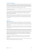
Table Of Contents
- Logic Pro X Effects
- Contents
- Chapter 1: Amps and pedals
- Chapter 2: Delay effects
- Chapter 3: Distortion effects
- Chapter 4: Dynamics processors
- Chapter 5: Equalizers
- Chapter 6: Filter effects
- Filter effects overview
- AutoFilter
- EVOC 20 Filterbank
- EVOC 20 TrackOscillator
- EVOC 20 TrackOscillator overview
- Vocoder overview
- EVOC 20 TrackOscillator interface
- EVOC 20 TrackOscillator analysis in parameters
- Use EVOC 20 TrackOscillator analysis in
- EVOC 20 TrackOscillator U/V detection parameters
- EVOC 20 TrackOscillator synthesis in parameters
- EVOC 20 TrackOscillator oscillators
- EVOC 20 TrackOscillator formant filter
- EVOC 20 TrackOscillator modulation
- EVOC 20 TrackOscillator output parameters
- Fuzz-Wah
- Spectral Gate
- Chapter 7: Imaging processors
- Chapter 8: Metering tools
- Chapter 9: MIDI plug-ins
- Chapter 10: Modulation effects
- Chapter 11: Pitch effects
- Chapter 12: Reverb effects
- Chapter 13: Space Designer convolution reverb
- Chapter 14: Specialized effects and utilities
- Chapter 15: Utilities and tools
- Appendix: Legacy effects

Chapter 5 Equalizers 105
Channel EQ parameters
The left side of the Channel EQ window features the Gain and Analyzer controls. The central area
of the window includes the graphic display and parameters for shaping each EQ band.
Channel EQ parameters
•
Master Gain slider and eld: Drag to set the overall output level of the signal. Use it after
boosting or cutting individual frequency bands.
•
Analyzer button: Turns the Analyzer on or o.
•
Pre/Post EQ button: Determines whether the Analyzer shows the frequency curve before or
after EQ is applied, when Analyzer mode is active.
•
Resolution pop-up menu: Choose the sample resolution for the Analyzer. Choose from the
following menu items: low (1024 points), medium (2048 points), and high (4096 points).
•
Band On/O buttons: Turn the corresponding band on or o. Each button’s icon indicates the
lter type:
•
Band 1 is a highpass lter.
•
Band 2 is a low shelving lter.
•
Bands 3 through 6 are parametric bell lters.
•
Band 7 is a high shelving lter.
•
Band 8 is a lowpass lter.
•
Graphic display: Shows the current curve of each EQ band. The scale is shown in dB.
•
Drag horizontally in the section of the display that encompasses each band to adjust the
frequency of the band.
•
Drag vertically in the section of the display that encompasses each band to adjust the gain
of each band (except bands 1 and 8). The display reects your changes immediately.
•
Drag the pivot point in each band to adjust the Q factor. Q is shown beside the pointer
when it is moved over a pivot point.
•
Frequency elds: Drag to adjust the frequency of each band.
•
Gain/Slope elds: Drag to set the amount of gain for each band. For bands 1 and 8, this
changes the slope of the lter.
•
Q elds: Drag to adjust the Q factor or resonance for each band—the range of frequencies
around the center frequency that are aected.