
10.6


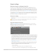


Table Of Contents
- Contents
- What’s new in Logic Pro
- Get started with Logic Pro
- Get started with Logic Pro overview
- Get started with the Logic Pro main window
- Get started with Logic Pro projects
- Get started with project playback in Logic Pro
- Get started with Logic Pro project properties
- Tracks
- Get started with patches
- Get started arranging regions in Logic Pro
- Editing regions
- Get started with Drummer in Logic Pro
- Get started with Smart Controls in Logic Pro
- Get started with Live Loops in Logic Pro
- Get started with mixing Logic Pro projects
- Get started with Apple Loops in Logic Pro
- Get started with Smart Tempo
- Get started sharing Logic Pro projects
- If you are upgrading
- Logic Pro basics
- What is Logic Pro?
- Logic Pro workflow overview
- Logic Pro interface overview
- Logic Pro main window interface
- Logic Pro Tracks area interface
- Logic Pro Library interface
- Logic Pro Inspector interface
- Logic Pro Mixer interface
- Logic Pro Smart Controls interface
- Editors
- Note Pads
- List Editors
- Logic Pro Loop Browser interface
- Browsers
- Logic Pro project basics
- Work with Logic Pro windows
- Open and close Logic Pro windows
- Move and resize Logic Pro windows
- Zoom Logic Pro windows
- Scale Logic Pro plug-in windows
- Move through display levels in Logic Pro
- Control Logic Pro windows using Catch modes
- Link windows in a Logic Pro project
- Control windows using screensets
- Work with tools in Logic Pro
- Logic Pro advanced tools and options
- Undo and redo edits in Logic Pro
- Manage Logic Pro content
- Content types
- Content locations
- Relocating the Sound Library
- Reinstalling the Sound Library
- Deleting Logic Pro content
- Open the Sound Library Manager
- Download additional content
- Download additional content in the Library or the Loop Browser
- Download all available sounds
- Relocate the Sound Library
- Reinstall the Sound Library
- How to get help for Logic Pro
- Connect external devices
- Logic Pro hardware connection overview
- Connect audio devices
- Using audio devices with Logic Pro overview
- Connect a microphone to a computer running Logic Pro
- Connect an electric instrument to a computer running Logic Pro
- Connect an audio interface to a computer running Logic Pro
- Connect speakers to a computer running Logic Pro
- Configure audio devices to use with Logic Pro
- Configure Apogee and Euphonix devices to use with Logic Pro
- Connect MIDI devices
- Work with projects
- Logic Pro projects overview
- Create Logic Pro projects
- Open Logic Pro projects
- Save Logic Pro projects
- Delete Logic Pro projects
- Play and navigate projects
- Play a Logic Pro project
- Set the playhead position in Logic Pro
- Control playback in Logic Pro with the transport buttons
- Use transport shortcut menus in Logic Pro
- Use transport keyboard shortcuts in Logic Pro
- Customize the Logic Pro control bar
- Change the LCD display mode
- Monitor and reset MIDI events in Logic Pro
- Use the cycle area in Logic Pro
- Use the Chase Events function in Logic Pro
- Control Logic Pro using Apple Remote
- Control Logic Pro projects using Logic Remote
- Set project properties
- Logic Pro project properties overview
- Set the tempo of a Logic Pro project
- Set the key and scale for a Logic Pro project
- Set the time signature of a Logic Pro project
- Set the sample rate of a Logic Pro project
- Set the start and end points for a Logic Pro project
- Set the playback volume of a Logic Pro project
- Manage projects
- Preview Logic Pro projects in the Finder
- Close Logic Pro projects
- View Logic Pro project information and reorganize memory
- Work with tracks
- Logic Pro Tracks overview
- Track basics
- Create tracks in a Logic Pro project
- Create tracks using drag and drop in Logic Pro
- Create tracks with a Sampler plug-in (single files only)
- Create a track with a Quick Sampler plug-in (single files only)
- Create a track with an Alchemy plug-in (single files only)
- Create a track with a Drum Machine Designer plug-in (single or multiple files)
- Create tracks with a Sampler plug-in (multiple files only)
- Add a track by dragging an audio file, region, or loop to the Tracks area
- Add a track by dragging a single file, region, or loop to the track header area
- Add a track by dragging multiple files, regions, or loops to the track header area
- Create tracks using existing channel strips in Logic Pro
- Assign tracks to different channel strips in Logic Pro
- Select tracks in Logic Pro
- Duplicate tracks in Logic Pro
- Rename tracks in a Logic Pro project
- Change track icons in a Logic Pro project
- Change track colors in a Logic Pro project
- Reorder tracks in a Logic Pro project
- Zoom tracks in Logic Pro
- Replace or double drum sounds in Logic Pro
- Use the track header controls
- Logic Pro track header overview
- Mute tracks in a Logic Pro project
- Solo tracks in a Logic Pro project
- Set track volume levels in a Logic Pro project
- Set track pan positions in a Logic Pro project
- Enable tracks for recording in Logic Pro
- Use input monitoring with audio tracks in Logic Pro
- Use track alternatives in Logic Pro
- Show track alternatives
- Add a track alternative
- Duplicate the active track alternative
- Choose a different track alternative
- Rename track alternatives
- Rename track alternatives using region names
- Show all existing track alternatives
- Hear an inactive track alternative
- Make a track alternative active
- Move or copy regions to the active alternative using key commands
- Delete all inactive track alternatives
- Turn off tracks in Logic Pro
- Protect tracks in Logic Pro
- Freeze tracks in Logic Pro
- Hide tracks in Logic Pro
- Delete tracks in a Logic Pro project
- Edit multiple tracks in a Logic Pro project
- Work with patches in the Library
- Logic Pro patches overview
- Choose patches in the Logic Pro Library
- Choose presets in the Logic Pro Library
- Search for patches by name in Logic Pro
- Merge patch settings in the Logic Pro Library
- Reset Logic Pro patches
- Save custom patches in a Logic Pro project
- Map performance patches in Logic Pro
- Use the Blocks and Bells performance patch
- Use the Bongos and Bongos Stick performance patches
- Use the Cajon performance patch
- Use the Claps and Snaps performance patch
- Use the Congas and Congas Bright performance patches
- Use the Shakers 1 and Shakers 2 performance patches
- Use the Tambourines performance patch
- Use the Timbales performance patch
- Work with Track Stacks
- Control timing with the groove track in Logic Pro
- Work with articulations
- Bounce tracks and regions in place
- Use selection-based processing in Logic Pro
- Export tracks and regions
- Edit Logic Pro track parameters
- Record your voice or a musical instrument
- Overview of recording in Logic Pro
- Record audio
- Record software instruments
- Before recording software instruments in Logic Pro
- Play software instruments in Logic Pro
- Record software instruments in Logic Pro
- Record additional software instrument takes in Logic Pro
- Overdub software instrument recordings in Logic Pro
- Spot erase software instrument recordings in Logic Pro
- Use Note Repeat in Logic Pro
- Record to multiple software instrument tracks in Logic Pro
- Replace software instrument recordings in Logic Pro
- Record multiple MIDI devices to multiple tracks in Logic Pro
- Record software instruments and audio simultaneously in Logic Pro
- Use step input recording in Logic Pro
- Use the metronome in Logic Pro
- Advanced recording techniques
- Comp your audio recordings
- Overview of comping in Logic Pro
- Preview take recordings in Logic Pro
- Create, save, edit, and rename comps
- Edit take regions
- Manage take folder contents
- Use loops and other media files
- Using loops and other media in Logic Pro
- Use Apple Loops in your projects
- Import and search for files
- Bookmarks in the Logic Pro All Files Browser
- Use the Project Audio Browser
- The Project Audio Browser in Logic Pro
- Add and delete audio files in Logic Pro
- Import an audio file into your project
- Import a Music Memos file
- Add an audio file to the Project Audio Browser
- Create a region from an audio file in the Project Audio Browser
- Delete a region from the Project Audio Browser
- Delete an audio file from the project or hard disk
- Delete sections of audio files that are no longer used in the project
- Play audio files in Logic Pro
- Sort, group, and rename audio files in Logic Pro
- Move, copy, and convert audio files in Logic Pro
- Export and import audio region information in Logic Pro
- Import compressed audio files into Logic Pro
- Supported media and file formats
- Arrange a project
- Logic Pro Arranging overview
- Work in the Tracks area
- Logic Pro Tracks area overview
- Position items using the ruler in Logic Pro
- Use alignment guides in Logic Pro
- Snap items to the grid in Logic Pro
- Vertically zoom the Logic Pro Tracks area
- Quantize regions in Logic Pro
- Use drag modes in Logic Pro
- Scrub a Logic Pro project
- Scroll and zoom the Logic Pro Tracks area
- Customize the Logic Pro toolbar
- Arrange regions in the Tracks area
- Logic Pro regions overview
- Select regions in the Logic Pro Tracks area
- Select parts of regions in the Logic Pro Tracks area
- Select parts of regions using the Marquee tool
- Select parts of regions using the marquee stripe
- Remove individual tracks from the selection
- Change the selection start or end point
- Move the entire selection
- Snap to the finest possible resolution in the current snap mode
- Snap to the division value shown in the LCD
- Set locators with a marquee selection
- Split regions at the selection border
- Cut and paste regions in the Logic Pro Tracks area
- Move regions in the Logic Pro Tracks area
- Add or remove gaps in a Logic Pro arrangement
- Delay region playback in the Logic Pro Tracks area
- Loop regions in the Logic Pro Tracks area
- Repeat regions in the Logic Pro Tracks area
- Resize regions in the Logic Pro Tracks area
- Resize a region
- Resize two adjacent regions
- Resize selected regions to the same absolute length
- Resize selected region start or end points to the playhead position
- Remove overlaps between regions
- Remove overlaps by reducing the length of the later region
- Lengthen regions to remove gaps between them
- Lengthen selected regions between locators
- Mute and solo regions in the Logic Pro Tracks area
- Time stretch regions in the Logic Pro Tracks area
- Split regions in the Logic Pro Tracks area
- Demix MIDI regions in the Logic Pro Tracks area
- Join regions in the Logic Pro Tracks area
- Create regions in the Logic Pro Tracks area
- Normalize audio regions in the Tracks area
- Create MIDI aliases in the Logic Pro Tracks area
- Clone audio regions in the Logic Pro Tracks area
- Convert repeated MIDI regions to loops in Logic Pro
- Color regions in the Logic Pro Tracks area
- Convert audio regions to Sampler zones in Logic Pro
- Rename regions in Logic Pro
- Delete regions in the Logic Pro Tracks area
- Create fades and crossfades on audio regions
- Remove silent passages from audio files
- Work with folders
- Work with groove templates
- Edit region parameters
- Edit audio regions in the Audio Track Editor
- The Audio Track Editor in Logic Pro
- Select regions in the Logic Pro Audio Track Editor
- Cut, copy and paste in the Logic Pro Audio Track Editor
- Move regions in the Logic Pro Audio Track Editor
- Trim regions in the Logic Pro Audio Track Editor
- Split, join regions in the Logic Pro Audio Track Editor
- Snap to zero in the Logic Pro Audio Track Editor
- Delete regions in the Logic Pro Audio Track Editor
- Use Flex Time and Pitch in the Audio Track Editor
- Automation in the Logic Pro Audio Track Editor
- Edit MIDI regions in the Piano Roll Editor
- Overview of the Piano Roll Editor in Logic Pro
- Open the Piano Roll Editor
- Switch the Piano Roll Editor to show drum names
- Switch the Piano Roll Editor to Collapse Mode view
- Open the Piano Roll Editor as a separate window
- Vertically resize the Piano Roll Editor
- Hide or show the local Piano Roll Editor inspector
- Set the Link mode for the Piano Roll Editor
- Change the background for the Piano Roll Editor
- Close the Piano Roll Editor
- Add and edit notes
- Add notes in the Piano Roll Editor in Logic Pro
- Select notes in the Piano Roll Editor in Logic Pro
- Snap to grid in the Piano Roll Editor in Logic Pro
- Move notes in the Piano Roll Editor in Logic Pro
- Copy notes in the Piano Roll Editor in Logic Pro
- Change pitch in the Piano Roll Editor in Logic Pro
- Resize notes in the Piano Roll Editor in Logic Pro
- Edit velocity in the Piano Roll Editor in Logic Pro
- Quantize timing in the Piano Roll Editor in Logic Pro
- Quantize pitch in the Piano Roll Editor in Logic Pro
- Change articulations in the Piano Roll Editor in Logic Pro
- Lock position in the Piano Roll Editor in Logic Pro
- Mute notes in the Piano Roll Editor in Logic Pro
- Change colors in the Piano Roll Editor in Logic Pro
- View Note Labels in the Piano Roll Editor in Logic Pro
- Delete notes in the Piano Roll Editor in Logic Pro
- Time stretch notes in the Piano Roll Editor in Logic Pro
- View multiple regions in the Piano Roll Editor in Logic Pro
- Split chords in the Piano Roll Editor in Logic Pro
- The Automation/MIDI area in the Piano Roll Editor in Logic Pro
- Open other editors from the Piano Roll Editor in Logic Pro
- Overview of the Piano Roll Editor in Logic Pro
- Add drummers to your project
- Overview of Drummer in Logic Pro
- Working with drummers and Drummer regions
- Drummers and the Drummer Editor in Logic Pro
- Choose genres and drummers in Logic Pro
- Choose drummer presets in Logic Pro
- Edit a drummer’s performance in Logic Pro
- Adjust the complexity and loudness of the performance
- Choose a pattern variation for acoustic drum or percussion instruments
- Choose a pattern variation for electronic drum or percussion instruments
- Mute or unmute a drum or percussion instrument
- Use a half time or double time variation for acoustic kick and snare drums
- Adjust the snare brush technique of drummers using a brush kit
- Edit fills and swing settings
- Edit other acoustic drum performance settings
- Edit other electronic drum performance settings
- Set Drummer to follow another track’s rhythm in Logic Pro
- Work with Producer Kits in Logic Pro
- Convert Drummer regions to MIDI in Logic Pro
- Edit the timing and pitch of audio
- Overview of Flex Time and Pitch in Logic Pro
- Edit the timing of audio
- Edit the pitch of audio
- Flex Pitch algorithm and parameters in Logic Pro
- Edit pitch using Flex Pitch in Logic Pro
- Edit audio pitch in the Logic Pro Tracks area
- Edit audio pitch in the Logic Pro Tracks area
- Quantize pitch in the Audio Track Editor in Logic Pro
- MIDI from audio using Flex Pitch in Logic Pro
- Change gain in the Logic Pro Audio Track Editor
- Use Varispeed in Logic Pro
- Advanced edit features
- Logic Pro advanced editors overview
- Event List
- Logic Pro Event List editor overview
- Event List display options
- Select and create events in the Event List
- Edit events in the Event List
- Event Types
- Use the Event Float window in Logic Pro
- Step Editor
- Logic Pro Step Editor Overview
- Create and edit steps in the Step Editor
- Change the Step Editor grid and step display in Logic Pro
- Create steps in the Step Editor in Logic Pro
- Select steps in the Step Editor in Logic Pro
- Delete steps in the Step Editor in Logic Pro
- Restore deleted steps in the Step Editor in Logic Pro
- Change step values in the Step Editor in Logic Pro
- Move and copy steps in the Step Editor in Logic Pro
- Protect the position of steps in Logic Pro
- Lane parameters
- Use Lane Sets in the Step Editor in Logic Pro
- Audio File Editor
- Logic Pro Audio File Editor overview
- Audio File Editor interface
- Play audio files in the Audio File Editor in Logic Pro
- Navigate audio files in the Audio File Editor in Logic Pro
- Make selections in the Audio File Editor
- Edit and process audio in the Audio File Editor
- Use commands to edit audio in Logic Pro
- Edit audio files with transient markers in Logic Pro
- Use the Audio File Editor Pencil tool in Logic Pro
- Trim or silence audio files in Logic Pro
- Set audio file levels in Logic Pro
- Normalize audio files in Logic Pro
- Add fades to audio files in Logic Pro
- Reverse audio in the Audio File Editor in Logic Pro
- Create Loops in the Audio File Editor in Logic Pro
- Undo Audio File Editor edits in Logic Pro
- Backup audio files in the Audio File Editor in Logic Pro
- Use an external sample editor with Logic Pro
- MIDI Transform window
- Logic Pro MIDI Transform window overview
- Use MIDI transform sets in Logic Pro
- Logic Pro MIDI Transform presets overview
- MIDI Transform window parameters
- MIDI Transform window examples in Logic Pro
- Add a mod wheel controller event (#1) with a value that matches the note’s velocity
- Create a transform set that fixes all note velocities to a defined amount
- Convert MIDI note events to MIDI controller 1 events
- Randomly change the pitch of MIDI note events
- Make note selections for edit operations
- Delete volume events (MIDI CC#7) from a MIDI region
- Delete all controller events from a region
- Create an ascending pitch pattern from notes of one pitch
- Experiment with the Double Speed preset in the Step Editor
- Mix a project
- Overview of mixing in Logic Pro
- Mixer channel strips
- Set channel strip volume and check levels
- Set channel strip input formats in Logic Pro
- Set channel strip pan or balance positions in Logic Pro
- Mute and solo channel strips in Logic Pro
- Work with plug-ins
- Overview of plug-ins in Logic Pro
- Add, remove, move, and copy plug-ins in Logic Pro
- Insert an instrument plug-in on a track using drag and drop in Logic Pro
- Insert a Quick Sampler plug-in (single files only)
- Insert an Alchemy plug-in (single files only)
- Insert a Drum Machine Designer plug-in (single or multiple files)
- Insert an instrument plug-in by dragging a single file, region, or loop
- Insert an instrument plug-in by dragging multiple files, regions, or loops
- Activate plug-ins on inactive channels
- Use the Channel EQ in Logic Pro
- Work in the plug-in window in Logic Pro
- Open a plug-in window (when it’s closed)
- Close a plug-in window
- Adjust plug-in parameters
- Undo a plug-in parameter change
- Redo a plug-in parameter change
- Hide or show the plug-in window header
- Adjust the size of a plug-in window
- Switch the plug-in parameter view
- Link or unlink plug-in windows
- Choose a source for a side chain signal into a plug-in
- Hide or show additional parameters (if available for the plug-in)
- Work with plug-in settings in Logic Pro
- Work with plug-in latencies in Logic Pro
- Work with Audio Units plug-ins
- Support for ARA 2 plug-ins in Logic Pro
- Use the Plug-in Manager in Logic Pro
- Open the Plug-in Manager
- Create a new category
- Rename an existing category
- Remove an existing category or plug-in
- Search for plug-ins by name
- Manually enable Audio Units plug-ins that fail the validation test
- Disable a plug-in
- Rescan a selection of plug-ins
- Copy a selection of plug-ins from a Manufacturer listing to a Category listing
- Move a selection of plug-ins from one Category to another Category
- Return to default Category and Manufacturer listings
- Work with channel strip settings in Logic Pro
- Load a channel strip setting
- Choose the next or previous channel strip setting
- Copy or paste a channel strip setting
- Paste only the plug-ins from a channel strip
- Paste only the sends from a channel strip
- Remove all insert effect plug-ins from a channel strip
- Remove any empty insert slots from a channel strip
- Remove any bypassed effect plug-ins from a channel strip
- Remove all sends from a channel strip
- Reset a channel strip setting
- Save a channel strip setting
- Delete a channel strip setting
- Save a channel strip setting as a performance
- Control channel strip signal flow in the Mixer
- Route audio via insert effects in Logic Pro
- Route audio via send effects in Logic Pro
- Adjust panning for sends independently in Logic Pro
- Use aux channel strips
- Use multi-output instruments in Logic Pro
- Use output channel strips in Logic Pro
- Define a channel strip’s stereo output in Logic Pro
- Define a channel strip’s mono output in Logic Pro
- Create tracks for signal flow channel strips in Logic Pro
- Work with Mixer groups
- Surround panning in the Mixer in Logic Pro
- Binaural panning
- Work with MIDI channel strips
- Customize the Mixer
- Use the I/O Labels window in Logic Pro
- Undo and redo Mixer and plug-in adjustments in Logic Pro
- Automate mix and effects settings
- Overview of automation in Logic Pro
- Track-based vs. region-based automation in Logic Pro
- Show automation curves in Logic Pro
- Choose automation modes in Logic Pro
- Add automation to tracks
- Add and adjust automation points in Logic Pro
- Add one or more automation points to an automation curve
- Add a series of MIDI data points using region-based automation
- Add a series of automation points using the Pencil Tool
- Add automation points at marquee borders
- Add automation points at region borders
- Add automation points at selection borders
- Adjust automation points
- Adjust MIDI values in region-based automation
- Adjust an automation point range in Logic Pro
- Record live automation in Logic Pro
- Add and adjust automation points in Logic Pro
- Select, copy, move, and delete automation
- Select, copy, and move automation in Logic Pro
- Select automation
- Select non-contiguous automation
- Select specific automation values within a time range
- Select all automation following an automation point or curve
- Copy automation within a track
- Copy automation between tracks
- Move automation
- Adjust automation curve symmetrically between two horizontally aligned points
- Create a vertical automation line
- Move regions with or without automation
- Move a region selection with its automation
- Bend an automation curve
- Change an automation curve into stepped automation
- Delete automation in Logic Pro
- Select, copy, and move automation in Logic Pro
- Snap automation to grid position in Logic Pro
- Edit in the Automation Event List in Logic Pro
- Write automation with controllers in Logic Pro
- Use Smart Controls
- Logic Pro Smart Controls overview
- Show Smart Controls for master effects in Logic Pro
- Choose a Smart Control layout in Logic Pro
- Automatic MIDI controller assignment in Logic Pro
- Map screen controls automatically in Logic Pro
- Map screen controls in Logic Pro
- Edit mapping parameters in Logic Pro
- Use parameter mapping graphs in Logic Pro
- Open the plug-in window for a screen control in Logic Pro
- Rename a screen control in Logic Pro
- Use articulation IDs to change articulations in Logic Pro
- Assign hardware controls to screen controls in Logic Pro
- Compare Smart Control edits with saved settings in Logic Pro
- Use the Arpeggiator in a Logic Pro project
- Automate screen control movements in Logic Pro
- Use Live Loops
- Logic Pro Live Loops overview
- Start and stop Live Loops cells in Logic Pro
- Work with Live Loops cells in Logic Pro
- Add a region from the Tracks area to the Live Loops grid
- Create new tracks when dragging multiple items to the Live Loops grid
- Copy and paste regions to cells in the Live Loops grid
- Copy regions within the cycle range to Live Loops
- Copy regions to Live Loops based on selection
- Import an audio file to an empty cell
- Convert Drummer and pattern cells to MIDI cells
- Extract loops from audio cells
- Create cells
- Add a cell from the Live Loops grid to the Tracks area
- Copy a scene to the Tracks area
- Create an Apple Loop from a cell
- Record to cells
- Change loop settings for cells in Live Loops for Logic Pro
- Change the start position of a cell
- Change the loop start position of a cell
- Change the loop length of a cell
- Change the cell length
- Set the Quantize Loop Start position
- Turn off cell looping
- View cell length and loop length as positions
- View start positions as an offset
- Change the resolution of the position and length values
- How the Live Loops grid and Tracks area interact in Logic Pro
- Edit Live Loops cells in Logic Pro
- Edit Live Loops scenes in Logic Pro
- Scene selection and focus
- Select scenes
- Change the focused scene in a multiple selection
- Trigger focused scene
- Copy currently playing cells to a scene
- Reorder scenes
- Duplicate scenes
- Insert an empty scene
- Add multiple empty scenes to the end of the grid
- Rename a scene
- Delete a scene
- Change the play mode for a scene
- Change the Quantize Start value for a scene
- Change the Quantize Start value or play mode for all scenes
- Work in the Cell Editor in Logic Pro
- Bounce Live Loops cells in Logic Pro
- Record a Live Loops performance in Logic Pro
- Change Live Loops view settings in Logic Pro
- Control Live Loops in Logic Pro with other devices
- Use Step Sequencer
- Logic Pro Step Sequencer overview
- Create Step Sequencer patterns in Logic Pro
- Pattern creation basics in Logic Pro
- Change the musical length of a pattern in Logic Pro
- Use Step Sequencer edit modes in Logic Pro
- Edit modes for both row types
- Edit modes for note rows
- Edit modes for automation rows
- View and edit multiple edit modes for a row using subrows
- Choose the edit mode for the pattern
- Change edit mode values for steps in the grid
- Show subrows for a row
- Change the edit mode for a subrow
- Add a subrow
- Delete a subrow
- Pattern creation examples
- Load and save patterns in the Logic Pro Step Sequencer
- Modify Step Sequencer pattern playback in Logic Pro
- Edit Step Sequencer steps in Logic Pro
- Edit Step Sequencer rows in Logic Pro
- Edit Step Sequencer pattern, row, and step settings in Logic Pro
- Customize the Step Sequencer interface in Logic Pro
- Edit global project settings
- Logic Pro global changes overview
- Use the global tracks
- Work with markers
- Build a project with arrangement markers
- Work with time and key signatures
- Work with tempo
- Logic Pro tempo overview
- Create tempo changes with the Tempo track
- Use the Tempo List
- Use Smart Tempo
- Match audio regions to the Logic Pro project tempo
- Match the tempo to an audio region in Logic Pro
- Use audio file tempo information in Logic Pro
- Record tempo changes in Logic Pro
- Use Tempo Operations
- Use the Logic Pro Tempo Interpreter
- Use the tempo fader in Logic Pro
- Work with transposition
- Work with beat mapping
- Control the volume of a Logic Pro project
- View and edit music notation
- Logic Pro music notation overview
- Work in the Score Editor
- Logic Pro Score Editor overview
- View tracks as music notation in Logic Pro
- Import MusicXML files to a Logic Pro project
- Position items (graphically) in the Logic Pro Score Editor
- Move and copy items in the Logic Pro Score Editor
- Move and copy items using the Layout tool
- Move items with key commands
- Copy and paste items via the Clipboard
- Move a note or symbol with the pointer
- Copy a note or symbol with the pointer
- Restrict movement to one direction (vertical or horizontal)
- Move items using key commands
- Paste the Clipboard contents into several regions
- Copy an entire musical passage to the same time position in another region
- Resize notes and symbols in the Logic Pro Score Editor
- Adjust display headroom in the Logic Pro Score Editor
- Repeat events in the Logic Pro Score Editor
- Insert items in multiple regions in the Logic Pro Score Editor
- Edit multiple items in the Logic Pro Score Editor
- Select multiple regions in the Logic Pro Score Editor
- Hide regions in the Logic Pro Score Editor
- Add notes to a score in Logic Pro
- Add notes and symbols from the Part box
- Logic Pro part box overview
- View score symbols in the Logic Pro part box
- View Part box symbol groups
- Reorder symbol groups in the Part box
- Display all symbol groups
- View symbol groups in a floating window
- Select score symbols using key commands
- Choose a score symbol set
- Create a new score symbol set
- Rename a score symbol set
- Delete the current score symbol set
- Show the inspector channel strips below the Part box
- Select score symbols in the Logic Pro Part box
- Add notes and rests from the Logic Pro Part box
- Add notes and symbols to multiple regions in Logic Pro
- Add key and time signature changes to a score in Logic Pro
- Key signature changes
- Time signature changes
- Add a key signature change in the Score Editor
- Change the key signature in Linear view
- Change the key signature in Wrapped view and Page view
- Change the time signature in Linear view
- Change the time signature in Wrapped view and Page view
- Add a time signature change in the Score Editor
- Change the clef sign in a score in Logic Pro
- Add dynamic marks, slurs, and crescendi to a score in Logic Pro
- Change the appearance of note heads in a score in Logic Pro
- Add accents and other symbols to notes in a score in Logic Pro
- Add trills, ornaments, and tremolo symbols to a score in Logic Pro
- Add sustain pedal markers to a score in Logic Pro
- Add chord symbols to a score in Logic Pro
- Add chord grids and tablature symbols to a score in Logic Pro
- Add bar lines, repeats, and coda signs to a score in Logic Pro
- Add page and line break symbols to a score in Logic Pro
- Edit notes in the Score Editor
- Select notes in the Logic Pro Score Editor
- Move and copy notes in the Logic Pro Score Editor
- Change note pitch, duration, and velocity in the Logic Pro Score Editor
- Change note articulations in the Logic Pro Score Editor
- Quantize the timing of notes in the Logic Pro Score Editor
- Edit note attributes
- Logic Pro Score Editor note attributes overview
- Change note heads in a score in Logic Pro
- Change note size and position in a score in Logic Pro
- Change how accidentals appear in a score in Logic Pro
- Control beaming in the Logic Pro Score Editor
- Change voice and staff assignments in the Logic Pro Score Editor
- Change the direction of ties in the Logic Pro Score Editor
- Change note syncopation and interpretation in the Logic Pro Score Editor
- Use independent notes in the Logic Pro Score Editor
- Change note color in the Logic Pro Score Editor
- Reset note attributes in the Logic Pro Score Editor
- Restrict note input to the current key in the Logic Pro Score Editor
- Control how ties are displayed in the Logic Pro Score Editor
- Add and edit tuplets in the Logic Pro Score Editor
- Override display quantization in the Logic Pro Score Editor
- Add grace and independent notes in the Logic Pro Score Editor
- Delete notes in the Logic Pro Score Editor
- Use automation in the Logic Pro Score Editor
- Add lyrics and text
- Logic Pro Score Editor lyrics and text overview
- Add lyrics to a score in Logic Pro
- Add and edit text
- Add automatic text to a score in Logic Pro
- Add global text to a score in Logic Pro
- Work with chord grids
- Logic Pro chord grids overview
- Logic Pro Instrument Editor for chord grids
- Logic Pro Chord Grid Selector
- Logic Pro Chord Grid Editor
- Edit chord grids in the Logic Pro Score Editor
- Create custom chord grids in the Chord Grid Editor
- Add and edit chord grid libraries in Logic Pro
- Import and export chord grid libraries in Logic Pro
- Edit score region parameters
- Logic Pro score region parameters overview
- Logic Pro Style region parameter
- Logic Pro Quantize region parameter
- Logic Pro Interpretation region parameter
- Logic Pro Syncopation region parameter
- Logic Pro No Overlap region parameter
- Logic Pro Max Dots region parameter
- Logic Pro Score region parameter
- Edit default score parameters for new regions in Logic Pro
- Work with staff styles
- Logic Pro staff styles overview
- Assign staff styles to tracks in Logic Pro
- Work in the Logic Pro Staff Style window
- Create staff styles in the Logic Pro Staff Style window
- Edit staff styles in the Logic Pro Staff Style window
- Edit staff style parameters in the Logic Pro Staff Style window
- Add and delete staffs or voices in the Logic Pro Staff Style window
- Copy staffs or voices in the Logic Pro Staff Style window
- Copy staff styles between Logic Pro projects
- Delete staff styles in Logic Pro
- Assign notes to voices and staffs in Logic Pro
- Display polyphonic parts on separate staffs in Logic Pro
- Change the staff assignment of score symbols in Logic Pro
- Beam notes across staffs in Logic Pro
- Use mapped staff styles for drum notation in Logic Pro
- Predefined staff styles used in Logic Pro
- Create scores and parts using score sets
- Logic Pro score sets overview
- Choose a score set in the Logic Pro Region inspector
- Create and delete score sets in Logic Pro
- Edit score set parameters in Logic Pro
- Change the instruments in a score set in Logic Pro
- Resize score sets in Logic Pro
- Create layouts for a score and its parts in Logic Pro
- Extract parts from a score in Logic Pro
- Import score sets from other Logic Pro projects
- Edit the score layout
- Share a Logic Pro score
- Customize the Score Editor
- Choose a color mode for the Logic Pro Score Editor
- Show folder contents in a Logic Pro score
- Display global tracks in the Logic Pro Score Editor
- Display instrument names in the Logic Pro Score Editor
- Display duration bars in the Logic Pro Score Editor
- Edit the length of duration bars in the Logic Pro Score Editor
- Display guide lines in the Logic Pro Score Editor
- Share projects
- Overview of sharing in Logic Pro
- Bounce projects
- Share songs to the Music app from Logic Pro
- Share songs from Logic Pro using AirDrop
- Share songs from Logic Pro using MailDrop
- Share songs to SoundCloud from Logic Pro
- Share a project to GarageBand for iOS from Logic Pro
- Export projects
- Work in surround
- Using Surround in Logic Pro
- Set up for surround
- Surround features
- Additional surround information
- Work in the Environment
- Overview of the Environment in Logic Pro
- Common parameters in the Logic Pro Environment
- Work with Environment layers
- Work with Environment objects
- Create your MIDI signal path
- Exchange Environments
- Customize the Environment in Logic Pro
- Environment objects reference
- Standard instrument objects
- Multi-instrument objects
- Mapped instrument objects
- Touch track objects
- Fader objects
- Fader objects in the Logic Pro Environment
- Use faders in the Logic Pro Environment
- Play back fader movements in the Logic Pro Environment
- Object groups in the Logic Pro Environment
- Fader styles in the Logic Pro Environment
- Fader: MIDI events in the Logic Pro Environment
- Fader: range, value as in the Logic Pro Environment
- Fader: filter in the Logic Pro Environment
- Vector fader in the Environment in Logic Pro
- Special faders in the Logic Pro Environment
- Cable switchers in the Logic Pro Environment
- Meta event faders in the Logic Pro Environment
- SysEx faders in the Logic Pro Environment
- SysEx messages in the Logic Pro Environment
- Special functions in the Logic Pro Environment
- Alias objects
- Ornament objects in the Logic Pro Environment
- GM mixer objects
- MMC record buttons in the Logic Pro Environment
- Keyboard objects in the Logic Pro Environment
- Monitor objects in the Logic Pro Environment
- Macro objects
- Arpeggiator objects
- Transformer objects
- Delay line objects
- Voice limiter objects
- Channel splitters in the Logic Pro Environment
- Chord memorizer objects
- Physical inputs in the Logic Pro Environment
- Sequencer inputs in the Logic Pro Environment
- MIDI click objects in the Logic Pro Environment
- Channel strip objects
- Video and synchronization
- Logic Pro video and synchronization overview
- Use movies in Logic Pro
- Logic Pro synchronization
- Preferences, project settings, and key commands
- Logic Pro preferences
- Overview of preferences in Logic Pro
- General preferences
- Audio preferences
- Devices preferences in Logic Pro
- General Audio preferences in Logic Pro
- Sampler preferences
- Audio Editing preferences in Logic Pro
- Output preferences in Logic Pro
- Bounce Extensions preferences in Logic Pro
- Input preferences in Logic Pro
- Audio File Editor preferences in Logic Pro
- MP3 preferences in Logic Pro
- Recording preferences in Logic Pro
- MIDI preferences
- Display preferences
- Score preferences in Logic Pro
- Movie preferences in Logic Pro
- Automation preferences in Logic Pro
- Control surface preferences
- My Info preferences in Logic Pro
- Advanced preferences in Logic Pro
- Project settings
- Overview of project settings in Logic Pro
- General settings in Logic Pro
- Synchronization settings
- Metronome settings in Logic Pro
- Smart Tempo settings in Logic Pro
- Recording settings in Logic Pro
- Tuning description and settings
- Audio Settings
- MIDI settings
- Score settings
- Movie settings in Logic Pro
- Assets settings in Logic Pro
- Key commands
- Key commands in Logic Pro
- Browse, import, and save key commands in Logic Pro
- Assign key commands in Logic Pro
- Copy and print key commands in Logic Pro
- Key command tables
- Global Commands key commands in Logic Pro
- Global Control Surfaces Commands key commands in Logic Pro
- Various windows key commands in Logic Pro
- Windows Showing Audio files key commands in Logic Pro
- Main Window Tracks and Various Editors key commands in Logic Pro
- Live Loops Grid key commands in Logic Pro
- Various Editors key commands in Logic Pro
- Views showing Time Ruler key commands in Logic Pro
- Main Window Tracks key commands in Logic Pro
- Mixer key commands in Logic Pro
- MIDI Environment key commands in Logic Pro
- Piano Roll key commands in Logic Pro
- Score Editor key commands in Logic Pro
- Event Editor key commands in Logic Pro
- Step Editor key commands in Logic Pro
- Step Sequencer key commands in Logic Pro
- Project Audio key commands in Logic Pro
- Audio File Editor key commands in Logic Pro
- Smart Tempo Editor key commands in Logic Pro
- Sampler key commands in Logic Pro
- Step Input Keyboard key commands in Logic Pro
- Tool key commands in Logic Pro
- Logic Pro preferences
- Use the Touch Bar with Logic Pro
- Use control surfaces
- Control surface requirements in Logic Pro
- Connect control surfaces in Logic Pro
- Add a control surface to Logic Pro
- Automatic assignment for USB MIDI controllers in Logic Pro
- Create control surface groups in Logic Pro
- Control surface inspector
- Overview of Control Surfaces preferences
- Control surfaces Modal dialog display in Logic Pro
- Control surface use tips in Logic Pro
- Control surfaces supported by Logic Pro
- Software and firmware
- Assign hardware controllers
- Overview of controller assignments in Logic Pro
- Controller Assignments Easy view
- Controller Assignments Expert view
- Use controller assignments Expert view in Logic Pro
- Controller assignments Expert view parameters in Logic Pro
- Assign and delete controllers in Expert view in Logic Pro
- Use controller assignments zones and modes in Logic Pro
- Controller assignments Control Name and Label fields in Logic Pro
- Controller assignments Flip Group and Exclusive parameters in Logic Pro
- Controller assignments Class pop-up menu parameters in Logic Pro
- Controller assignments Expert view Input Message parameters in Logic Pro
- Controller assignments OSC Message Paths in Logic Pro
- Controller assignments Expert view Value parameters in Logic Pro
- Assign controller buttons to key commands in Logic Pro
- Glossary

1031Logic Pro User Guide
• Jog resolution depends on horizontal zoom checkbox: Turn on to link the precision of
scrubbing (using the Jog/Shuttle Wheel of your control surface) with the horizontal
zoom level of Logic Pro. Your control surface must feature a Jog/Shuttle Wheel (or
similar control) for this to have an effect. To retain a consistent resolution, regardless of
Logic Pro window zoom levels, deselect this checkbox.
• Pickup Mode checkbox: Turn on to use your control surface in Pickup mode (if this
mode is available).
Some control surfaces, typically those without motorized faders or knobs, do not
show parameter changes—caused by playing back existing automation data—on their
interface. Such control surfaces usually offer a Pickup mode. In Pickup mode, the
controller must reach (“pick up”) the current value before the value starts to change.
This feature prevents sudden jumps of parameter values caused by playing back
automation. Your device may provide a display (usually a pair of arrow LEDs) that
indicates the direction or distance you need to move the controller, in order to match
the settings shown in Logic Pro (also known as NULL). Once you have matched the
onscreen values, you can create or edit automation data. When Pickup mode is turned
off, adjusting a fader modifies the parameter immediately (which can result in parameter
value jumps).
• Flash Mute and Solo buttons checkbox: Turn on to make the Mute and Solo buttons on
the control surface blink (flash) on and off when mute or solo modes are engaged.
• Multiple Controls per Parameter pop-up menu: Choose the maximum number of
encoders used for each parameter when editing plug-ins or audio instruments. The
choices are:
• 1: Parameters are always displayed using one encoder per parameter, with the least
space available for the parameter name and value in the LCD.
• 2: On each unit, encoders 1 and 2 are used for the first parameter, encoders 3 and 4
for the second, and so on.
• 4: On each unit, encoders 1 to 4 are used for the first parameter, encoders 5 to 8 for
the second, and so on.
• 8: On each unit, encoders 1 to 8 are used for the first parameter, encoders 9 to 16
for the second, and so on.
When multiple encoders are used per parameter, the encoders are divided into groups
(1/2, 3/4, 5/6, 7/8, for example). The first encoder of each group controls the parameter
shown in the display. The remaining encoders are inactive. Using more than one
encoder per parameter shows fewer parameters at any given time, but you gain space
on the LCD to cater for longer parameter names and values. The more control surfaces
you have within a control surface group, the more you benefit from this feature.
• Only when all parameters fit on one page checkbox: Turn on to use the defined number
of encoders only when there are sufficient encoders available to show all parameters
without changing pages.
For example, if you have a MackieControl and two MackieControlXTs (giving you a
total of 24 encoders), a plug-in with 13 parameters is shown with one encoder per
parameter. Eleven encoders remain unused. A plug-in with 11 parameters is shown with
two encoders per parameter. Two encoders remain unused (as do the inactive encoders
of the subdivisions mentioned above). When this parameter is turned off, multiple
encoders are used for each parameter, which may require scrolling. This is not the case
if only one encoder is used for each parameter.