
Installation guide


Chapter 1: Hardware Connections and MC Client Setup 1
Chapter 1: Hardware Connections and
MC Client Setup
Schematics and parts are listed for each DAW setup in Appendix B, “DAW Parts Lists and Schematics.”
Connecting the MC
To connect the MC:
Unpack the MC from its packaging and select a place to put it. The MC should go on a hard flat surface in order to allow proper
ventilation. (System 5-MC has its own frame for the MC and CM408T modules).
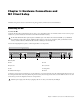
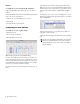
Use the following diagram as a guide to connecting the MC to its components.
1 VGA
2 Keyboard
3 USB
4 Talkback Mic Output
5 LAN
6 Footswitch
7 Headphone
8 DC In
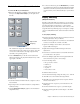
Plug the power supply into the DC In port on the right side as you look at the back panel. Be careful plugging this in as the con-
nector has pins that can be bent easily. When the pins are seated, twist the ring on the connector’s side until it locks. Do not turn
on the MC yet; network configuration must be completed first.
The MC and CM408T modules require sufficient ventilation space on the bottom. The MC has detachable feet for standalone
users without a System 5 frame, but the CM408T modules do not. If you do not use a System 5 frame, you must have at least
1 inch of clearance under the CM408T modules and MC or damage to the units may occur.
MC back panel
123 4 5 678
Attach the power supply to the MC before plugging it into an AC outlet, or the unit may be damaged.