
User`s guide


2
2
2
222
2
Flowcharts and TablesTroubleshooting
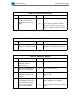
Table 30. No Pickup From Lower Cassette (Continued)
Step Check Result Action
5 Remove the paper pickup
block and maintain pickup
connectivity (see
“Troubleshooting Tips” in
this chapter). Place probes
on the solder side of the
pickup controller board on
J603-4 (GND) and the
power supply side of diode
D606. Does the voltage
measure 5 V when you
switch on the printer?
Yes Perform the first module exchange
listed below. If the problem still per-
sists, reinstall the original module and
perform the next exchange.
• Replace the sheet feeder controller
board.
• Replace the sheet feeder pickup
solenoid.
• Replace the sheet feeder controller
block.
• Remount and/or replace the pickup
shaft gear and roller.
6 Place probes between pins
J201-1 (GND) and J201-7
(+5 V) on the DC controller
board. Does the voltage
measure 5 V?
No
Ye s
Perform the first module exchange
listed below. If the problem still per-
sists, reinstall the original module and
perform the next exchange.
• Replace the I/O board
• Replace the DC controller board.
Replace the pickup controller board.