
User`s guide


2
2
2
222
2
Flowcharts and Tables
Troubleshooting
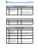
Table 29. No Pickup From Standard Cassette (Continued)
Step Check Result Action
6 Disconnect J201 on the DC
controller board. Place
probes between pins
J201-1 (GND) and
J201-13 (+24 V) on the
male connector on the
board. Does the voltage
measure 24 V?
No
Ye s
Replace the DC controller board.
Replace the pickup-to-DC controller
board cable.
7 Place probes between pins
J201-1 (GND) and J201-7
(+5 V) on the male
connector on the board.
Does the voltage measure
5 V?
No Replace the DC controller board.
8 Reconnect J201. Remove
the paper pickup block and
maintain pickup connectiv-
ity. Measure the voltage
between J601-11 (GND)
and J601-13
(+24 V) on the pickup
controller board. Does the
voltage measure 24 V?
No Replace the pickup-controller-to-DC-
controller-board cable.
9 Place probes between pins
J601-1 (GND) and J601-7
(+5 V). Does the voltage
measure 5 V?
No Replace the pickup-controller-to-DC-
controller-board cable.
10 Place probes between pins
J601-1 (GND) and J601-9
(+24 V). Does the voltage
measure 24 V?
No
Ye s
Replace the pickup controller board.
Perform the first module exchange
below. If the problem persists, reinstall
the original module and perform the
next exchange:
• Replace the pickup motor.
• Replace the pickup sensor board.