
User`s guide


2
2
2
222
2
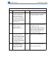
Flowcharts and Tables
Troubleshooting
Table 7. Laser/Scanner Error
Step Check Result Action
1 Remove the rear panel and
I/O shield. Are the DC
controller board connec-
tors J205 and J206
secure?
No Secure the cables.
2 Remove the top cover and
delivery roller assembly.
Are all three laser/scanner
assembly connectors
secure?
No Secure the cables.
3 Remove the two cables
that run from the DC
controller board to the
laser/scanner assembly
and check the resistance of
each. Is the resistance
approximately 1 ohm or
less for each wire?
No
Ye s
Replace the defective cable.
Replace the laser/scanner assembly.
If the problem persists, reinstall the
original module and replace the DC
controller board.
Table 8. Main Motor Error
Step Check Result Action
1 Remove the rear panel and
I/O shield. Is the main
motor cable secure at J211
on the DC controller board?
No
Ye s
Secure the cable.
Perform the first module exchange
listed below. If the problem persists,
reinstall the original module and per-
form the next exchange:
• Replace the main motor.
• Replace the DC controller board.
• Replace the main motor cable.