
User`s guide


Flowcharts and TablesTroubleshooting
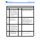
Table 6. Fuser Assembly Error (Continued)
Step Check Result Action
3 Remove the fuser assembly
and let it cool. Measure the
resistance between J743-6
and J743-7 on the fuser.
(Refer to the wiring diagram
for illustration and pin layout
of connector J743.) Does the
resistance measure between
180 and 280 k
Ω
?
No Disconnect J744 and check for same
resistance. Replace the thermistor or
the connector cable, as needed.
4 Measure the resistance
between J743-1 and J743-8
on the fuser. Does the
resistance measure
approximately 3
Ω
or less?
No If there is continuity through the heater
bulb, replace the heater bulb. If there
is continuity across the
thermoprotector, replace the fuser
connector cable. If there is not conti-
nuity across the thermoprotector
replace the thermoprotector, and
proceed to the next step.
5 Reinstall the fuser. Place
probes between J212-1
(/FSRD) and TB201-6 (GND)
on the DC controller board.
Does the voltage change
from approximately 5.1 V to
1.5 V a few seconds after the
printer starts up?
No Replace the DC controller board.
6 Place probes between
J212-2 (RLD) and TB201-6
(GND). Does the voltage
measure approximately
2.1 V?
No
Yes
Replace the DC controller board.
Replace the power supply.