
Users Manual

RF1276D27 Long Distance Transceiver module V4.0
- 12 - 2016-6-12
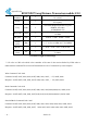
Central Mode Command Code: 0x04
Command: 0xAF, 0xAF, 0x00, 0x00, 0xAF, 0x80, 0x04, 0x02, 0x00, 0x00, 0x93, 0x0D, 0x0A
Response.: 0xAF, 0xAF, 0x00, 0x00, 0xAF, 0x00, 0x04, 0x02, 0x00, 0x00, 0x93, 0x0D, 0x0A
Node Mode Command Code: 0x05
Command: 0xAF, 0xAF, 0x00, 0x00, 0xAF, 0x80, 0x05, 0x02, 0x00, 0x00, 0x94, 0x0D, 0x0A
Response.: 0xAF, 0xAF, 0x00, 0x00, 0xAF, 0x00, 0x05, 0x02, 0x00, 0x00, 0x94, 0x0D, 0x0A
Please note that the working modes changed by the 0x03, 0x04 and 0x05 commands will not be written
into nonvolatile memory so the working mode will be restored to the former mode before change after
power-off. Users can use the WRITE command to change the working mode of module to standard mode
or low power mode but the sleep mode will be restored to standard mode after next power-on even if the
WRITE command is used.
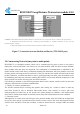
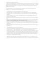
9. Application Schematic:
The connection schematic between RF1276D27 and MCU or terminal is shown as below.
The parameter of RF1276D27’serial port must match with MCU or terminal’s (RF1276D27 has the same
serial port baud rate and parity style with MCU or terminal). Two or more RF1276D27s in a system should
have the same parameters such as TX/RX frequency, air date rate and RF channel.