TA-500 Badge Reader Installation and Configuration Guide DSI Version 2.0 – 2.
06/05/2009 AD0842-20705 Copyright © 2006 API Healthcare Corporation This document is copyrighted by API Healthcare Corporation and all rights are reserved. This document may not, in whole or part, be reproduced, stored in a retrieval system, or transmitted, in any form or by any means, electronic, mechanical, recording, or otherwise, without prior written consent from API Healthcare.
TABLE OF CONTENTS THE TA-500 DEVICE.................................................................................................1 SUPPORTING DOCUMENTATION .............................................................................................. 1 PARTS IDENTIFICATION - FRONT ............................................................................................. 2 PARTS IDENTIFICATION – BACK ..............................................................................................
BADGE DOES NOT WORK IN DEVICE ............................................................................. 50 BADGE REGISTRATION ..................................................................................................... 50 DISPLAY WINDOW MESSAGES ........................................................................................ 51 NOT ABLE TO COMMUNICATE WITH THE DEVICE .................................................... 51 PARTS MAINTENANCE ..............................................
1 Chapter 1 THE TA-500 DEVICE Observe basic safety precautions when using electrical equipment. Please read all instructions first. Warranty will be void if device is wholly or partially inoperable as a result of not following these instructions. If you have any questions contact the API Healthcare Customer Support. This document contains specification, configuration, and wall mounting instructions for the TA-500 series.
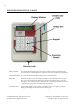
2 PARTS IDENTIFICATION - FRONT Display Window The Display Window displays the current date and time and messages identifying the success or failure a badge registration. Prompts for data entry also display in the window. Valid/Invalid LEDs The valid and invalid LEDs light to signify valid and invalid entries. Badge Slot Used with magnetic or bar code badges, the badge is swiped through the slot to register.
3 Keypad The keypad is used to enter additional information at the device. Interaction with the device may include registering additional information about a shift or submitting nonproductive time. Number Pad ............... Used to record values at the displayed prompts. CLR Key .................... The Clear Key is used to remove information currently displayed on the device. ENT Key.................... The Enter Key is used to save the entered data or to move to the next prompt. F1 Key .................
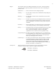
4 PARTS IDENTIFICATION – BACK Cable Entry The network cable providing power and network is routed through this location. Wall Mounting Holes The unit is mounted to the wall. This part of the plate faces the wall. Cable Channels Channels are provided for mounting the device on a solid surface. TA-500 Badge Reader (DSI Version 2.0-2.3) Installation and Configuration Guide Confidential – API Healthcare Corporation Copyright © 2006. All rights reserved.
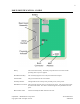
5 PARTS IDENTIFICATION – INSIDE Battery The location of the battery. The battery keeps the internal clock and calendar operating when no power is applied. Read Head Assembly The read head (magnetic or bar code) is located below this plate. Serial Number The general location of the serial number. Proximity Indicator The light indicates the activity of the proximity reader, when present. RJ45 Ethernet Connector The location the network cable is connected to the device.
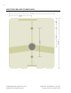
6 MOUNTING BRACKET DIMENSIONS TA-500 Badge Reader (DSI Version 2.0-2.3) Installation and Configuration Guide Confidential – API Healthcare Corporation Copyright © 2006. All rights reserved.
7 COMMUNICATION CONFIGURATION DIAGRAMS Power Over Ethernet HUB Power Over Ethernet Line Injector Confidential – API Healthcare Corporation Copyright © 2006. All rights reserved.
8 DEVICE SPECIFICATIONS Display 2 line by 16-character negative mode Liquid Crystal Display. Clock Dallas DS1307 Real-Time Clock (1): 56 Bytes SRAM (Battery Backed) Storage 1500 clockings Keypad Includes digits 0-9, clear key (CLR) enter key (ENT), and four additional function keys Card Magnetic Stripe: ABA/ISO2, track 2 used Bar Code: 3 of 9, Interleaved 2 of 5, Code 128 Infrared reader Proximity: Contact API Healthcare for additional information.
9 FCC RULES FCC Interference Statement (Part 15.105 (a)) This equipment has been tested and found to comply with the limits for a Class A digital device, pursuant to Part 15 of the FCC Rules. These limits are designed to provide reasonable protection against harmful interference when the equipment is operated in a commercial environment.
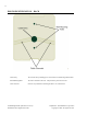
10 BADGE REGISTRATION The following summarizes the registration of the badge: Magnetic Holding the magnetic stripe away from the display window (facing the blue arrow), insert and slide the badge through the device's vertical slot in a smooth downward motion. Bar code Holding the bar code away from the display window (facing the blue arrow), insert and slide the badge through the device's vertical slot in a smooth downward motion.
11 RETURNING DEVICE FOR SERVICE Prior to returning a device to API Healthcare for service, contact API Healthcare Customer Support. A representative reviews several troubleshooting steps with you. In the event the device must be returned to API Healthcare for service, a Return of Merchandise Authorization (RMA) Number must be issued. IMPORTANT: Any equipment received without an RMA number is returned to the customer without review.
12 Notes TA-500 Badge Reader (DSI Version 2.0-2.3) Installation and Configuration Guide Confidential – API Healthcare Corporation Copyright © 2006. All rights reserved.
13 Chapter 2 DEVICE INSTALLATION DEVICE INSTALLATION GUIDELINES Comply with all applicable laws, ordinances, building codes, and zoning regulations. For IP communications, the device must be within 100 meters of a network closet. Use only the supplied mounting bracket with this device. Avoid areas of high magnetism. Avoid areas with asbestos or lead. Avoid areas that can disrupt electrical/network connectivity (i.e. by a MRI lab, large motors, etc.).
14 WALL MOUNTING PROCEDURES INSTALLATION CONSIDERATIONS Review the following considerations before installing the device on any surface. NOTE: Proper on-site technical and physical considerations must be taken into account based on your needs. The mounting area must be flat and vertical. The device's case is designed to provide maximum cooling when mounted to a flat surface. Mount the back panel to wall. Do not add spacers to angle the bracket in any way.
15 INSTALLATION: TA-500 COMMUNICATING VIA POE Obtain the following: Device with back plate Security Key 2 Mounting Screws Ferrite PoE Endspan to Midspan Adapter Single Gang Electrical box (optional for storage) Philips Head screw driver. Hand drill Pencil or other marking tool. Installation: 1. On the wall perform one of the following: Install the Single Gang Electrical box Mark the wall where the back plate is to be placed and mark the 2 holes to drill.
16 3. Install the ferrite. With 1-¼" of network cable in front of the ferrite, wrap the remaining cable 3 times around the ferrite. Close the ferrite. 4. Attach the PoE Endspan to Midspan Adapter. 5. When an electrical box is used, insert the ferrite first, then the adapter in the box. 6. Route the Ethernet cable from the Endspan to Midspan Adapter through the entry on the back panel. 7. Mount the back plate to the Electrical box or wall with the 2 supplied screws. 8.
17 INSTALLATION: TA-500 COMMUNICATING VIA POE LINE INJECTOR Obtain the following: Device with back plate Security Key 2 Mounting Screws Ferrite Line Injector Single Gang Electrical box (optional for storage) Philips Head screw driver. Hand drill Pencil or other marking tool. Installation: 1. On the wall perform one of the following: Install the Single Gang Electrical box Mark the wall where the back plate is to be placed and mark the 2 holes to drill. Drill the 2 mounting holes.
18 3. Install the ferrite. With 10" of network cable in front of the ferrite, wrap the remaining cable 3 times around the ferrite. Close the ferrite. 4. When an electrical box is used, insert the ferrite in the box. 5. Route the Ethernet cable through the entry on the back panel. 6. Mount the back plate to the Electrical box or wall with the 2 supplied screws. 7. Connect the Ethernet cable to the device. Verify information displays on the display window to indicate the device has power. 8.
19 Notes Confidential – API Healthcare Corporation Copyright © 2006. All rights reserved.
20 Notes TA-500 Badge Reader (DSI Version 2.0-2.3) Installation and Configuration Guide Confidential – API Healthcare Corporation Copyright © 2006. All rights reserved.
21 Chapter 3 CONFIGURATION SETTINGS Configuration to communicate to the device is performed either at the device or using Telnet. Note: The Setup Badge used for the Employee Information Station or TA20 badge reader may also be used. SUPERVISORS MENU ON DEVICE The Supervisors Menu is available for defining parameters used on the device. Perform the following to access the Supervisors Menu on the device: 1. Hold down the F1 key until the display changes from 'Present Badge' to 'Supervisor PIN'. 2.
22 3. MAC Address. Press 3 to display the MAC Address assigned to the device. Press the ENT key to return to the Network Type menu. 4. IP Address. Press 4 to view the current IP address used by the device. Press the ENT key to return to the Network Type menu. 5. Subnet. Press 5 to view the current Subnet address used by the device. Press the ENT key to return to the Network Type menu. 6. Gateway. Press 6 to view the current Gateway address used by the device.
23 3. Device Version 1. App Version. Press 1 to view the current application version number for the program installed on the device. Press the ENT key to return to the Device Version menu. 2. Boot Version. Press 2 to view the current boot version number for the program installed on the device. Press the ENT key to return to the Device Version menu. 3. DSI Version. Press 3 to view the current DSI version number for the program installed on the device. Press the ENT key to return to the Device Version menu.
24 2. LEDs. Press 2 to test the operation of the red and green LEDs. 1. Green LED. Press 1 to toggle the green LED on and off. 2. Red LED. Press 2 to toggle the red LEN on and off. 3. Both LEDs. Press 3 to toggle both the red and green lights on and off. Enter to Exit. Press the ENT key to return to the Diagnostics menu. 3. LCD Screen. Press 3 to test the LCD panel display. The top and bottom LCD alternately display. 4. Keypad Press 4 to test the keypad.
25 9. Reset. Press 9 to display the available menu items for resetting the device. 1. Fac Defaults. Press 1 to reset the device using the factory default. This clears any configuration data including the IP settings, badge configuration, and prompt data. 2. Reset Device. Press 2 to reset the CPUs operating on the device. This option does not clear any data, it only restarts the device. 3. IP Firmware Update. Press 3 to update the IP firmware on the device. 4. Reset Password.
26 TELNET MENU Ability to configure the device is available by using Telnet. Perform the following to access the menu via Telnet. 1. Ensure the device is powered and communicating on the network. 2. Open a Command Prompt window. From the Start menu select All Programs, Accessories, and then Command Prompt. 3. Enter one of the following commands: "telnet Cnnnnnn 9999" where Cnnnnnn is the hostname. The default hostname is Cnnnnnn where nnnnnn are the last 6 digits of the MAC address on the device.
27 MENU OPTIONS The initial menu displays a summary of the current settings for the device. CURRENT TA500 DEVICE SETTINGS -------------------------------------------------MAC Address: 00-11-22-33-44-55 Current IP Address: 1.7.7.170 Current Subnet Mask: 255.255.255.0 Current Gateway: 1.7.7.1 Current DNS: 0.0.0.0 Hostname: C334455 Comms Version: 0.0.0.
28 When selecting #2 to configure DHCP; enter the hostname. The default hostname is Cnnnnnn where nnnnnn is the last six digits of the MAC address. A valid hostname contains 1 to 16 digits. Press ENT to move to the next line. When no data is entered, the current setting remains. Method[1 – 2]: 2 Address assignment set to: DHCP Please enter Hostname: [2] Advanced Menu Options CURRENT DEVICE SETTINGS --------------------------------------------------MAC Address: 00-11-22-33-44-55 Current IP Address: 1.7.7.
29 [1] Change IP Port Configuration. Enter 1 to configure the IP Port configuration. Select [2] for UDP. Press enter to reach the option 'Please enter the UDP remote port. Enter the value and press Enter to complete the entry. The other settings are not used. For the Remote Port, when the value is configured with 0, the device acquires the value configured within the communications software. When the value is configured manually, it must match the value in the communications software. 0 is the default.
30 Notes TA-500 Badge Reader (DSI Version 2.0-2.3) Installation and Configuration Guide Confidential – API Healthcare Corporation Copyright © 2006. All rights reserved.
31 Chapter 4 ADDITIONAL FEATURES COMPLETE ENTRY KEY (RAPID ENTRY KEY) Employees may use this key to quickly complete a productive entry versus pressing the ENT key or allowing the device to time out. Badging Example 1 Swipe badge Press the F4 key to complete the entry Badging Example 2 Swipe badge Enter Special Code entry Press the F4 key to complete the entry The Complete Key (Rapid Key) is configurable on each device. When enabled, the F4 key is not available for a function key.
32 AUTOMATICALLY ACCEPT BADGE REGISTRATION The typical operation of the badge reader is when a badge is registered at the device, additional prompts for information display. When no entry for these prompts is entered, the registration is automatically accepted after several seconds of inactivity. The employee may also select the Complete Key (Rapid Entry Key) F4, when enabled, to record the transaction.
33 Chapter 5 TA-500 ADMINISTRATION UTILITY The TA-500 Administration Utility provides a means for configuring and verifying the current configuration of your TA-500 device. This stand-alone utility may connect to a device configured in the system database or manually by the device Hostname/IP address. INSTALLATION Workstation requirements include: 1. 2. Microsoft® Windows® 2000 or greater Microsoft® .NET Framework 1.1 (Service Pack 1) Execute the setup TA500AdminSetup.exe from the ..\Setups\TA500
34 3. Select the option for choosing the devices, enter the necessary information, then select Next to continue. Choose devices from a list in my database. Use this option to connect to your Time and Attendance database and choose from the list of configured devices. Select the type of database (SQL or Oracle) in use, then enter the connection information. SQL Database Server Name of the server the time and attendance database resides.
35 4. Select the option to perform operations on the device, then select Next to continue. Express Setup This option is not available when the 'I want to specify the devices manually option' is selected on the previous screen. Use this option to automatically setup the selected device. The latest values stored in the database are used or the user is prompted for information when necessary. Confidential – API Healthcare Corporation Copyright © 2006. All rights reserved.
36 The following configuration screen appears when the Express Setup or Update Reader Information option is selected. Use Database Values Indicate whether to not the information for this section is obtained from the database. RAM Version Version number referenced for the RAM. The value needs to match the database. For customers with the TA20 model badge reader, this value must match the value on the TA20. For all other customers use the value API-B22 ROM Version Version number referenced for the ROM.
37 Badge Type Enabled Magnetic Indicate whether or not the magnetic swipe is enabled on the device. When not checked, the magnetic swipe is disabled. Barcode Indicate whether or not the barcode swipe is enabled on the device. When not checked, the barcode swipe is disabled. Proximity Indicate whether or not the proximity reader is enabled on the device. When not checked, reading proximity badges is disabled.
38 Update Reader Information Select this option to configure various settings on the device. The following options are available for selection. More than one option may be selected. Update DSI Select this option to update the DSI file on the device, only devices with a DSI not matching the file selected are updated. Choosing the Force DSI Update forces the file to be updated on the device regardless of the current version. Enter the location and name of the DSI file to update.
39 Update Badge Formats Select this option to upload a badge file (Badge.dat) to the device. Enter the location and name of the Badge.dat to update. Use the available Browse button to locate the file. Note: For the api LaborWorkx system the badge format may also be updated by using the Update Badge File option in the Device Manager. Update Reader Configuration Select this option to configure additional reader options and features.
40 Get Version Select this option to retrieve information regarding the current DSI version operating on the device. Get Badge Formats Select this option to retrieve the current badge format configured on the device. Get Reader Configuration Select this option to retrieve information regarding the various reader configuration settings. Export Transactions This option provides the ability to export transactions from the device to format specified. The following options are available for selection.
41 5. Select the device(s) to configure then Next to continue. Only devices listed in the Selected Devices window are updated. Review the following to become familiar with the various screen functions. When the 'Choose devices from a list in my database ' option is selected. Devices Window Displays all devices currently online and configured within the database. The available information includes the number assigned to the device, the description, and the IP address/host name assigned to the device.
42 When the 'I want to specify the manually' option is selected. Add button Enter the host name or IP address of the Ta-500 device in the data entry field, then click Add to add the device to the Selected Devices window. Pressing the ENT key also adds the device to the Selected Devices listing. Please note, communication needs to be established to the device in order to add it. Selected Devices Window Displays all devices currently selected to be updated.
43 6. All selected devices are listed with the device id, device name, address, status, and overall progress. Select Next to start the update process. The Status and Overall Progress fields are updated during the processing. The devices are processed in groups. The arrow keys to the right of the display may be used to move devices in the list, allowing you to order the devices in a different order.
44 Notes TA-500 Badge Reader (DSI Version 2.0-2.3) Installation and Configuration Guide Confidential – API Healthcare Corporation Copyright © 2006. All rights reserved.
45 Chapter 6 PROCEDURES PREPARING DEVICE FOR SERVICE Use the Supervisor Menu on the device or connect via Telnet to configure the following information: 1. Network Type. Configure the method the device is communicating; either by DHCP (default setting) or with a static IP address. Supervisor Menu Option #2 IP Settings, #1 Network Type, #2 Set Network Telnet Menu Option #1 Change Network Configuration 2. Network Settings.
46 4. Communication Software. Within the communication software, add the device if does not currently exist. api LaborWorkx System Version 8.01.04.02 and greater add the device with the following settings: Hardware Classification: Series 500 IP Device Series: EIS Version 8.01.04.01 and less add the device with the following settings: Hardware Classification: TA20 IP Device Series: L Payrollmation System (NT) Release 6.05.
47 REMOVING CLOCKINGS FROM TRAINING DEVICE To configure a device for training purposes, configure as you would for any live device. Badgings occurring during training are typically not posted to the live environment. To prevent any badgings from being posted in the system, the device needs to be de-activated within the communications software. A device can hold approximately 1500 badgings before it becomes full.
48 DEVICE CONFIGURATION The following indicates the location for configuring the various device settings. Automatically Accept Transaction Use the TA-500 Administrator to enable/disable the feature. Use the Update Reader Configuration option. When enabled, no prompts for information appear. Badge Format For the api LaborWorkx System log into the Device Manager and use the Upload Badge File option. The information is updated from the database.
49 Reset Device Supervisor Menu, option #7 Diagnostics, #9 Reset, #2 Reset Device. Telnet Menu, option #2 Advanced Menu Options, option 2 Restart Device. Disconnect power to the device. Server IP Port on Device Supervisor Menu, Option #2 IP Settings, #8 Remote Port. Telnet Menu, Option #2 Advanced Menu Options, #2 UDP, press Enter to reach the prompt 'Please Enter the UDP remote port' option. Enter the value and press Enter to use the default settings for the remaining prompts.
50 TROUBLESHOOTING The following summarizes some of the initial steps needed for troubleshooting the device. BADGE DOES NOT WORK IN DEVICE Is the device power on? Badges do not read if there is no power to the device. Does the display window display "Present Badge"? If the device is currently within a configuration screen, badgings are not accepted. When was the last time the device was cleaned? Refer to the Maintenance section of this manual for cleaning information.
51 DISPLAY WINDOW MESSAGES Memory is 90% Full The device is running low on data storage memory due to a number of badgings already collected in the device. The device is still able to record badgings until it is full. The device should be polled to collect all data currently in the device. Memory Full The device's memory is full. No new badges are accepted until the data is collected from the device.
52 Notes TA-500 Badge Reader (DSI Version 2.0-2.3) Installation and Configuration Guide Confidential – API Healthcare Corporation Copyright © 2006. All rights reserved.
53 Chapter 7 PARTS MAINTENANCE CLEANING/SCHEDULED MAINTENANCE To ensure trouble-free operation, the following procedures provides for proper operation and adequate air-flow. READHEAD-MAGNETIC Frequency: At least once a month under ideal conditions. Perform more often if the reader is subject to high concentrations of airborne particles (i.e. grease or dust), or has a greater than average use. Materials: Magnetic Cleaning card Compressed air Important: Never reuse a cleaning card. 1.
54 CASE The case should also be cleaned on a routine basis. Cleaning solution should Remove oil, dirt, grease, and other contaminants. Leave no residual film. Not harm plastic and vinyl surfaces. Not harm the most delicate electronic and precision equipment, including magnetic tape heads. BATTERY REPLACEMENT CAUTION: Risk of explosion if battery is replaced by an incorrect type. Dispose of used batteries according to the instructions.
55 3. Perform the following at the device. A. Use the Security key to remove the Security Lock screw from the base of the device. B. Carefully lift the device from the wall mount. C. Unplug the RJ45 network connection from the inside of the device. D. Lay the device face down on a flat surface. Confidential – API Healthcare Corporation Copyright © 2006. All rights reserved.
56 E. Using the non-metallic tool with a flat head, carefully remove the battery from the device. F. Insert a new battery in the device. G. Plug in the RJ45 network connection. Ensure the device has power. H. Place the device on the wall mounting bracket. I. 4. Replace the Security Lock screw removed in Step 3A. Set the date and time on the device using one of the following methods: Using the Supervisor's Menu, use Option #5 from the Main menu to configure the Date and Time.
57 READ HEAD REPLACEMENT (MAGNETIC OR BAR CODE) Replacement of the read head does not affect the program in the device. No badgings are lost with this installation. MATERIALS NEEDED Security Key New Read Head Assembly Service cart or other flat surface. READ HEAD REPLACEMENT Perform the following at the device. 1. Use the Security key to remove the Security Lock screw from the base of the device. 2. Carefully lift the device from the wall mount.
58 3. Unplug the RJ45 network connection from the inside of the device. 4. Lay the device face down on a flat surface. 5. Disconnect the read head wire connector from the main circuit board. Bar Code TA-500 Badge Reader (DSI Version 2.0-2.3) Installation and Configuration Guide Magnetic Confidential – API Healthcare Corporation Copyright © 2006. All rights reserved.
59 6. Locate the silver plate connected to the inside of the device cover. Remove the four screws connecting the plate to the device cover. 7. Remove the two screws connecting the read head to the silver plate. 8. Remove the old Read Head Assembly. 9. Connect the new Read Head Assembly to the silver plate with the two screws removed in a previous step. 10. Place the read head in the device. Ensure the read head is facing the correct direction.
60 12. Connect the 5-wire connector from the new read head to the main circuit board. Tuck the wires between the read head mounting plate and the circuit board. Bar Code Magnetic 13. Plug in the RJ45 network connection. Ensure the device has power. 14. Swipe a badge to verify operation. 15. Place the device on the wall mounting bracket. 16. Replace the Security Lock screw removed in Step 1. TA-500 Badge Reader (DSI Version 2.0-2.
61 Notes Confidential – API Healthcare Corporation Copyright © 2006. All rights reserved.
62 Notes TA-500 Badge Reader (DSI Version 2.0-2.3) Installation and Configuration Guide Confidential – API Healthcare Corporation Copyright © 2006. All rights reserved.