
Installation Manual

Last Revision: 11/5/2009 Copyright 2009 API Healthcare Corporation.
API Internal Document – Company Confidential Information
Page 4of 4
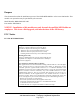
3. Place the TA-500 main circuit board in the case in the normal manner. Press down the TA-500 board to
ensure it makes contact with the tape on the RF module.
4. Install the screws to mount the main board to the case.
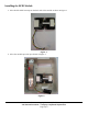
Figure 3.
5. Connect the cable from the RFID module to the COM2 connector as shown in Figure 3.
6. Complete final assembly of the unit.
Testing the RFID Module
1. Apply power and wait for the unit to boot up.
2. Enter Diagnostic Mode:
a. Hold the F1 key until the display shows: DIAGNOSTIC PIN
b. Enter the PIN number by pressing the following keys: 415049<ENT>
c. Press 1 (BADGE)
d. Press 1 (RAW DATA)
3. Hold the test badge near the front plate of the reader until it displays: BAR SUCCESS.
4. Verify the number displayed matches the number printed on the test card.
5. This completes test of the module.