
user manual
Rev. C4, 10/09 FLX Series
9
Automation Products Group, Inc.
APG...Providing tailored solutions for measurement applications
Tel: 1/888/525-7300 • Fax: 1/435/753-7490 • www.apgsensors.com • sales@apgsensors.com
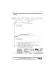
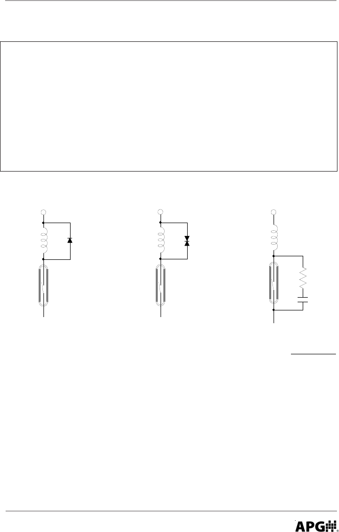
• Circuit Protection
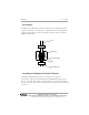
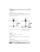
WARNING!
DO NOT EXCEED CONTACT RATINGS! When an inductive load is used
(e.g. a motor, a coil, or an electromagnetic relay), a back electromotive
force of several hundred volts (energy stored in the inductance) arises
when the contacts are opened. This results in considerable decrease in
contact life. The same result arises even when a resistive load is used
with a high voltage or a large current. The figures below show circuits for
protecting the reed switch(s) from the back electromotive force.
L
C
R
E
C = I
R = Approx.
10 x I (I + 50/E)
E
Protecting Circuit Using CR
Protecting Circuit Using Varistor
Protecting Circuit Using Diode
2
/10 (uF)
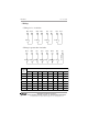
Code A & B Switches
Max. contact capacity 70 VA AC,
Max. switching current 220 VAC 0.5 A, 120 VDC 0.5 A
Code C Switches
Max. contact capacity 110 VA AC,
Max. switching current 220 VAC 0.5 A, 115 VDC 0.5 A