AUTOMATION P R O D U C T S G R O U P, I N C. Operator’s Manual FLR Series Magnetic Float Sensors 9003284 Rev. A5, 10/09 Automation Products Group, Inc. APG...Providing tailored solutions for measurement applications Tel: 1/888/525-7300 • Fax: 1/435/753-7490 • www.apgsensors.com • E-mail: sales@apgsensors.
FLR Series Rev. A5, 10/09 Table of Contents Warranty ......................................................................................... 3 Description ...................................................................................... 4 Installation ................................................................................... 5-6 Wiring .............................................................................................. 7 Circuit Protection .......................................
Rev. A5, 10/09 FLR Series • Warranty and Warranty Restrictions APG warrants its products to be free from defects of material and workmanship and will, without charge, replace or repair any equipment found defective upon inspection at its factory, provided the equipment has been returned, transportation prepaid, within 24 months from date of shipment from factory.
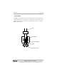
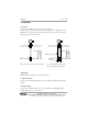
FLR Series Rev. A5, 10/09 • Description The FLR series instruments contain reed switches in the stem and permanent magnets in the floats. As the float rises or falls with the level of the liquid, the magnet inside the float act on the reed switch inside the stem to provide the SPST switching action. Stem Reed Switch Permanent Magnet Float Float Travel-Stop Automation Products Group, Inc. APG...
Rev. A5, 10/09 • FLR Series Installation - Unpacking When unpacking the instrument, exercise care not to subject the instrument to mechanical shock. After unpacking, visually inspect the instrument for damage. - Environment The FLR series sensors should be installed in an areas indoor or outdoor which meets the following conditions: 1. Non-hazardous area. 2. The medium temperature does not exceed -400F to 1850F (-140C to 850C).
FLR Series Rev. A5, 10/09 • Installation - Location Do not locate the FLR series sensor near inlets/outlets. If there is surface wave action, then use a time-delay relay or stilling tube. If a stilling tube is used, drill vent holes in the tube and use a spacer to assure the float has free travel inside the tube. Inflow Inflow Stilling Tube Spacer Wave action may cause switch to chatter. Use a stilling tube or time-delay relay to prevent switch chatter.
Rev.
FLR Series Rev. A5, 10/09 • Circuit Protection WARNING! DO NOT EXCEED CONTACT RATINGS! When an inductive load is used (e.g. a motor, a coil, or an electromagnetic relay), a back electromotive force of several hundred volts (energy stored in the inductance) arises when the contacts are opened. This results in considerable decrease in contact life. The same result arises even when a resistive load is used with a high voltage or a large current.
Rev. A5, 10/09 FLR Series • Field Adjustment Of Actuation Point(s) The FLR sensors are designed to allow field adjustments of the actuation points by moving the floats and reed switches. This section contains two procedures for making field adjustments. NOTE: FLR units without housings are hermetically sealed and cannot be field adjusted. Procedure one should be used under the following conditions: a. You want to move the actuation point relative to the factory settings. b.
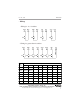
FLR Series Rev. A5, 10/09 2. Determine the location of the new actuation point. The actuation point is located at the center point between the float stops. Marks of previous stop locations 85 mm 85 mm New Actuation Point 3. Loosen the retaining hex screws on the float stops and slide the stops exactly the same distance along the stem to their new locations. Re-secure the stops to the stem. For example (refer to drawing above): Suppose the actuation point needs to be adjusted 85 mm lower on the stem.
Rev. A5, 10/09 FLR Series 4. Once the stops and float are set in the desired location, the reed switch assembly inside the stem needs to be adjusted to match the new actuation point. To access the reed assembly, you will need to remove the two screws that secure the terminal mounting plate to the housing. 5. Carefully remove the terminal mounting plate along with the wiring and internal reed switch assembly from the stem of the FLR.
FLR Series Rev. A5, 10/09 6. Carefully lay the reed switch assembly on a clean surface and remove the tape securing the wires to the assembly rod. Do not cut into the wires! 7. If you look closely at the reed switch assembly rod, you will notice a black mark at each reed switch location. During factory calibration, these marks are used to align the center of each reed switch with the desired actuation point.
Rev. A5, 10/09 FLR Series • Field Adjustment Of Actuation Point(s) Procedure Two: 1. Determine the desired actuation point. 2. Loosen the retaining screws on float stops that need to be repositioned. 3. Slide the float along the stem until the float’s center is aligned with the desired actuation point. 4. Re-secure the float stops 9 mm above and below the new float position (refer to drawing below). NOTE: The 9 mm distance between the float and stops is critical for the switch to operate reliably.
FLR Series Rev. A5, 10/09 5. With the float and stops in place at the new actuation point, the internal reed switch needs to be repositioned to match the new actuation point. Remove the two screws that secure the terminal mounting plate to the housing (shown above). 6. Carefully remove the terminal mounting plate along with the wiring and internal reed switch assembly from the stem of the FLR. Keep the assembly straight and take care not to bend or put stress on the reed switches.
Rev. A5, 10/09 FLR Series 7. Measure the distance from the bottom of the stem to the new actuation point. The actuation point is at the center position between the float stops. In the example above, the actuation point is at 250 mm. 8. A brass rod inside the stem holds the reed switches in place. The location of the switch needs to be adjusted to match the new actuation point. Determine which switch type you are using and continue to the step indicated below. CODE “A & B” (approx.
FLR Series Rev. A5, 10/09 Normally Open Switching for Code “A” & “B” Switches 8a. For “normally open” (NO) switching (code A & B switches), subtract 6 mm from the measurement taken in step 7 and record the result. This distance will be used to adjust the reed switch along the internal brass rod. The 6 mm is subtracted to compensate for the plug in the bottom of the stem. Refer to drawings below. Brass Rod Plug Approx.
Rev. A5, 10/09 FLR Series Normally Closed Switching for Code “A” & “B” Switches 8b. For “normally closed” (NC) switching (code A & B switches), subtract 18 mm from the measurement taken in step 7 and record the result. This distance will be used to adjust the reed switch along the internal brass rod. The 18 mm is subtracted to compensate for both the offset of the reed switch from the actuation point (-12 mm), and the plug in the bottom of the stem (-6 mm). Refer to drawings below.
FLR Series Rev. A5, 10/09 Normally Open Switching for Code “C” Switches 8c. For “normally open” (NO) switching (code C switches), subtract 3 mm from the measurement taken in step 7 and record the result. This distance will be used to adjust the reed switch along the internal brass rod. The 3 mm is subtracted to compensate for both the offset of the reed switch from the actuation point (+3 mm), and the plug in the bottom of the stem (-6 mm). Refer to drawings below. Brass Rod Plug Approx.
Rev. A5, 10/09 FLR Series Normally Closed Switching for Code “C” Switches 8d. For “normally closed” (NC) switching (code C switches), subtract 12 mm from the measurement taken in step 7 and record the result. This distance will be used to adjust the reed switch along the internal brass rod. The 12 mm is subtracted to compensate for both the offset of the reed switch from the actuation point (-6 mm), and the plug in the bottom of the stem (-6 mm). Refer to drawings below. Brass Rod Plug Approx.
FLR Series Rev. A5, 10/09 9. Using the distance you derived in step 8, measure from the bottom of the reed switch assembly and mark the center rod at that location. 10. Remove the tape securing the reed switch to the assembly rod. Be careful not to cut any of the wires or to put pressure in the reed switch. Automation Products Group, Inc. APG...Providing tailored solutions for measurement applications 20 Tel: 1/888/525-7300 • Fax: 1/435/753-7490 • www.apgsensors.com • sales@apgsensors.
Rev. A5, 10/09 FLR Series 11. Slide the reed switch along the rod until the center lines up with the mark you make on the rod in step 9. Re-secure the wires to the center rod with electrical tape. 12. Carefully reinsert the reed switch assembly into the stem and test the switch action. 13. If the actuation point needs fine tuning, remove the reed assembly from the stem and make any necessary adjustments to the reed switch position. 14. Reassemble the unit. Automation Products Group, Inc. APG...
FLR Series Rev. A5, 10/09 • Inspection and Maintenance Periodic inspection is necessary to keep your FLR unit in good working order. CAUTION! Do not remove the housing cover until the power supplied to the unit is turned off. 1. Keep the sensor clean. Never leave the housing cover off. If the cover becomes damaged or is misplaced, order a replacement immediately. If sediment or other foreign matter is trapped between the stem and the float, detection errors may be caused. Keep the float and stem clean. 2.
Rev. A5, 10/09 • FLR Series FLR Specifications Maximum Number Switching Points 7 Resolution +/- 1/16” (2mm) Field Adjustable Actuation Levels Yes Maximum Length 153 in. Maximum Process Temperature -400 to 1850F Housing Material Die Cast Aluminium Hazardous Rating None Housing Rating NEMA 4 Contact Rating: Code A & B Switch Max. contact capacity Max. switching current 70 VA AC, 200 VAC 0.5 A, 120 VDC 0.5 A Code C Switch Max. contact capacity Max. switching current 110 VA AC, 220 VAC 0.
FLR Series Rev. A5, 10/09 Automation Products Group, Inc. APG...Providing tailored solutions for measurement applications 24 Tel: 1/888/525-7300 • Fax: 1/435/753-7490 • www.apgsensors.com • sales@apgsensors.
Rev. A5, 10/09 FLR Series Automation Products Group, Inc. APG...Providing tailored solutions for measurement applications Tel: 1/888/525-7300 • Fax: 1/435/753-7490 • www.apgsensors.com • sales@apgsensors.
FLR Series Rev. A5, 10/09 Automation Products Group, Inc. APG...Providing tailored solutions for measurement applications 26 Tel: 1/888/525-7300 • Fax: 1/435/753-7490 • www.apgsensors.com • sales@apgsensors.
Rev. A5, 10/09 FLR Series Automation Products Group, Inc. APG...Providing tailored solutions for measurement applications Tel: 1/888/525-7300 • Fax: 1/435/753-7490 • www.apgsensors.com • sales@apgsensors.
AUTOMATION P R O D U C T S G R O U P, I N C. APG...Providing tailored solutions for measurement applications Automation Products Group, Inc. Tel: 1/888/525-7300 1/435/753-7300 Fax: 1/435/753-7490 e-mail: sales@apgsensors.com www.apgsensors.com Automation Products Group, Inc. 1025 W. 1700 N.