
user manual Owner's manual

Rev. A2, 11/06 DCU-1104 and DCU-1108
27
Automation Products Group, Inc.
APG...Providing tailored solutions for measurement applications
Tel: 1/888/525-7300 • Fax: 1/435/753-7490 • www.apgsensors.com • sales@apgsensors.com
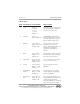
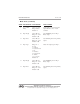
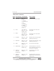
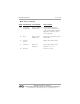
• Mode Sheet (continued)
MODE DESCRIPTION PARAMETERS EXPLANATION
15 Trip 2 Type Range = 0 - 7
0 - near
1 - exclusive
2 - hysteresis near
3 - far
4 - inclusive
5 - hysteresis far
6 - disable
7 - loss of echo
Default = 0
16 4mA* Units = Mode 1
Range = 0 - 9999
Default = 3.00
17 20mA* Units = Mode 1
Range = 0 - 9999
Default = 4.00
18 4mA Trim Range = 0 - 9999
Default = 5200
19 20mA Trim Range = 0 - 9999
Default = 9208
20 Offset Range = 0 - 9999
Default = 0
21 Offset Polarity Range = neg, pos
Default = neg
22 Calibration Range = 0 - 9999
Above the Default = 1
Decimal Point
23 Calibration Range = 0 - 9999
Below the Default = 0
Decimal Point
Selects the output type for Trip 2.
Sets the end point for the 4 mA
analog limit.
Sets the end point for the 20 mA
analog limit.
Fine tunes the 4 mA analog output.
(calibrated at the factory)
Fine tunes the 20 mA analog output.
(calibrated at the factory)
Sets an offset for the display.
Selects the direction of the offset.
Add or Subtract the offset from the
distance before displaying.
Sets the integer portion of the
calibration factor.
Sets the fractional portion of the
calibration factor. (decimal point is
assumed, 9999